Enterprise Data Center Design
Kapitel 5 fra CCDP ARCH bogen.
Contents
Cisco Catalyst 6500 serie switches Cisco Data Center Technologies
Designing The Core and Aggregation Layers
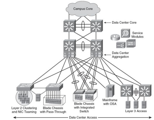
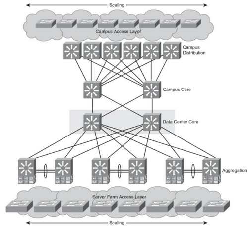
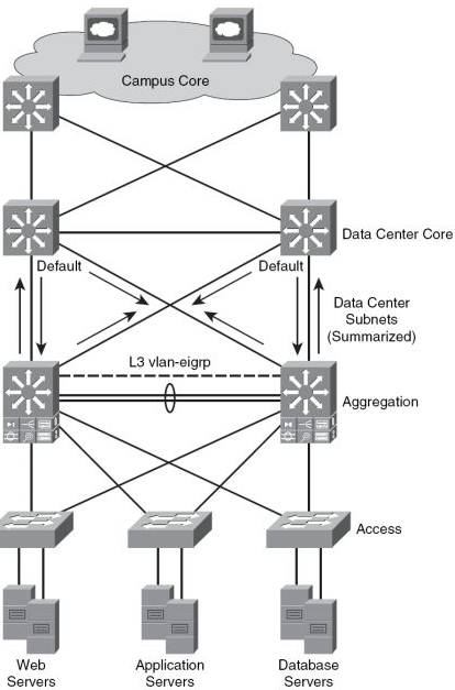
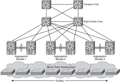
Data Center arkitekturen er baseret på en tre lags model.
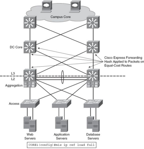
- Core laget består af høj-hastigheds OSI lag 3.
- Aggregation laget forbinder Access-Laget med enten OSI lag 2 eller OSI lag 3.
- Access Laget giver fysisk forbindelse til Serverne.
fordele ved tre-lags modellen
- Hvis det er nødvendigt at samme VLAN skal være på flere Access Switche samtidig kan Aggregation-Switchene-----
Data Center Core layer design
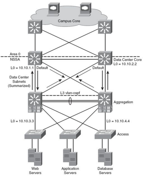
Routnings Protokoller
OSPF
EIGRP
Aggregation Layer
Spanning tree design
Cisco anbefaler at benytte sig af RPVST+.
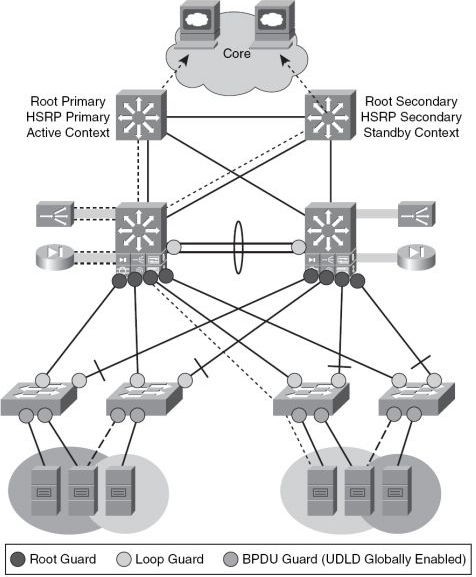
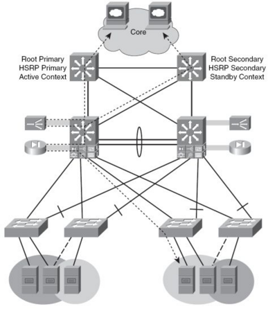
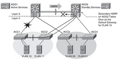
Aktiv STP,HSRP og Service Context Alignment
Active/Standby Service Module Design
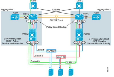
I tegningen herunder er den ene Aggregation Switch Active og den anden Standby for al trafikken fra Access laget.
- Cisco 6500 med FSWM 2.x
Active/Active Service Module Design
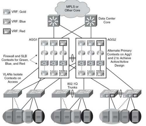
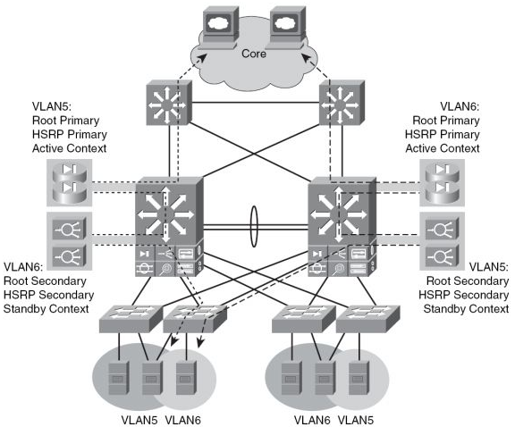
I tegningen herunder er begge Aggregation Switche Active for hver deres VLAN's.
- Cisco 6500 med FSWM 3.1
|
Establisheing Inbound Path Prefenrece
Route Health Injection(RHI) tillader at en Cisco CSM/ACE i en 6500 switch installerer en hoste route til den virtuelle server. /32 routen fjerner problemer med asymmetriske routing.
Anvendelse af VRF (MPLS) i Data centeret
Access Lag
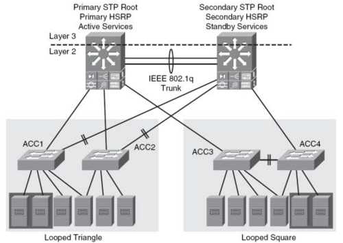
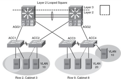
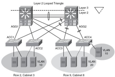
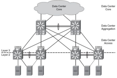
Lag 2 - Looped design
I Lag to Looped Design er VLAN's termineret i Aggregation laget og Lag 2 services som NIC teaming, Clustering og Statefull Services som for eksempel Firewall, Server Load Balancing, SSL kan udføres på ISO lag 2. Lag tre Routning foregår på Aggregations laget.
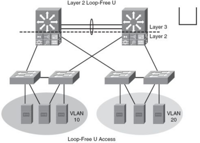
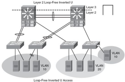
Lag 2 - Loop frit design
I Lag to Loop frit design er der ikke VLAN på Aggregationslaget modsat Looped design (Se overnfor). Ved omvendt U er det dog muligt at have VLAN på Aggregationslaget. Lag to services er supporteret. Lag tre Routning foregår på Aggregations laget.
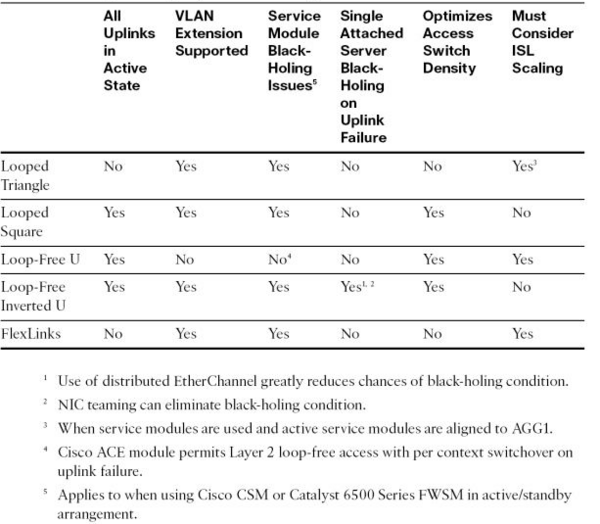
Sammenligning af lag to Access designs
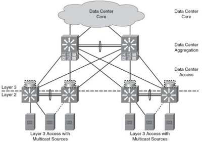
Lag 3 på Access laget
Statefull Services som kræver lag to konnektivitet kan ikke udføres af Aggregationslaget hvis Lag tre Routning foregår på Access-laget.
Multicast Source Support
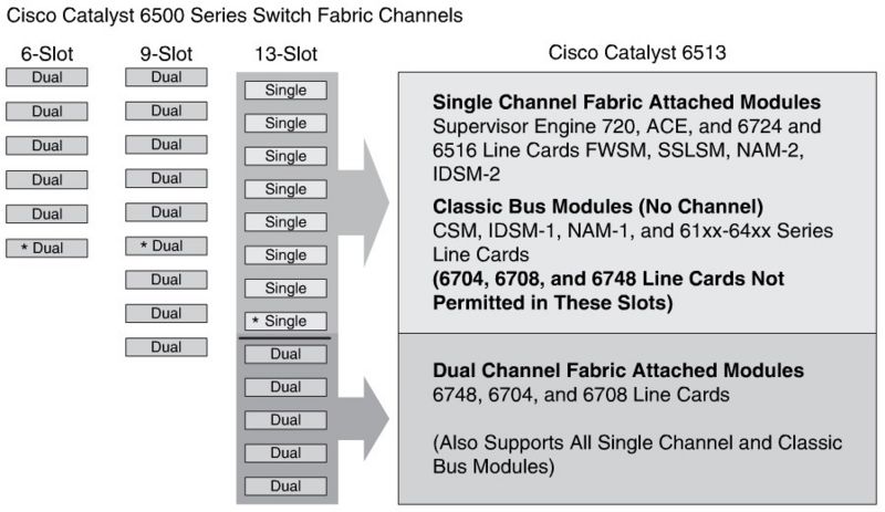
6500 Services Module Placement Considerations
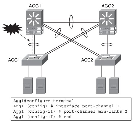
Optimizing EtherChannel U tilization with Min-Links
STP in the DataCenter
RSTP is the most common STP used in the data center today, and is the implementation recommended by Cisco for the enterprise data center.
- It scales to a large size (about 10,000 logical ports).
- Coupled with UDLD, loop guard, root guard, and BPDU guard, it provides a strong and stable Layer 2 design solution.
- It is a proven solution that is easy to implement and scale.
MST is not as common in the enterprise data center because of its characteristics:
- It permits large-scale STP implementations (about 30,000 logical ports). This is typically more useful for service providers and application service providers.
- It isn’t as flexible as RSTP.
- It has service module implications for firewalls in transparent mode.
- It is more commonly used with service providers and application service providers.
Limit HSRP instances: The number of VLANs is typically tied to the number of
HSRP instances. Cisco recommends a maximum of 500 HSRP instances on the Catalyst 6500 series Supervisor Engine 720 with default timers.
Use MST if it meets the requirements: If you cannot support the STP scaling issues with RSTP, you can consider implementing MST.
 This article is under development....