3-tier design
From Teknologisk videncenter
Setup
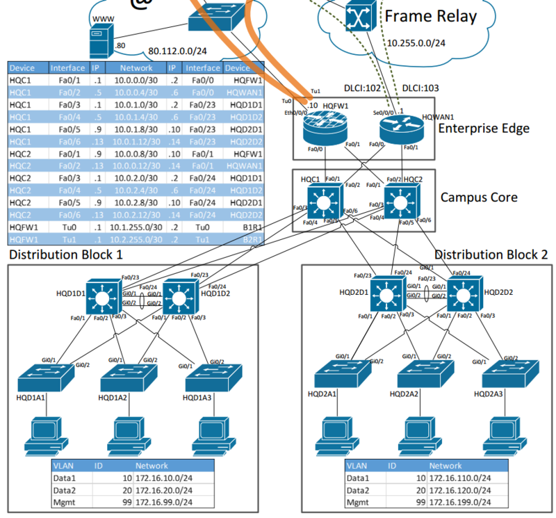
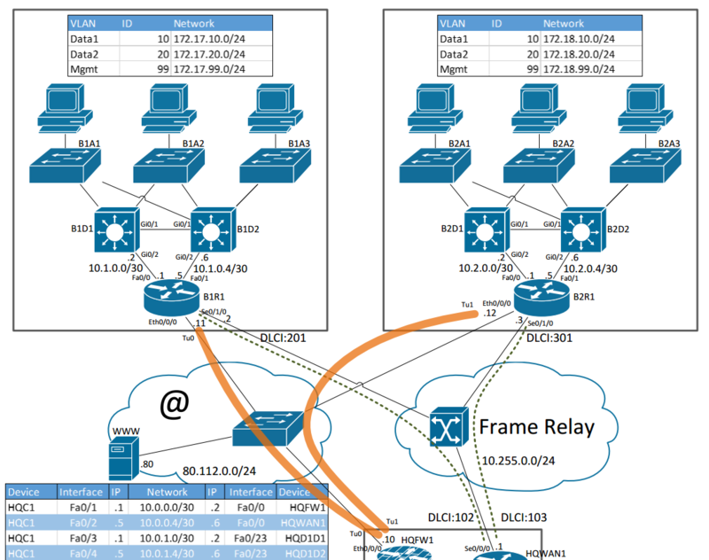
We are going to configure the following 3-tier design in steps
PNG diagram
Download the setup as a PDF
Campus Configuration
Configure the campus core and the 2 distribution blocks with OSPF and the other needed protocols.
- Configure Hostnames on all devices in the Campus Config/Info
- Configure IP addresses on all devices
- Configure VTP configuration Info
- Configure Distribution Switch 1 to be the STP Master for alle PVST+ instances Config/Info
- Configure HSRP on all SVI interfaces Config/Info
- Configure Etherchannel between the distibution switches Config/Info
- Configure trunk ports between the Distribution and Access Switches Config/Info
- Configure the access switches with an ip address in the MGMT VLAN Config
- Configure ports for the clients Config/Info
- Configure OSPF Info
- Configure OSPF area 0 on all interconnects Config
- Configure OSPF area 1/2 on the distribution blocks
- Do Not use stub areas
- Configure a static default route on HQFW01 point to 80.112.80.1Config
- Redistribute the default route into OSPF Config
- Configure NAT/PAT on HQFW01 Config/Info
Branch Configuration
- Add another ethernet interface to the HQFW01 Router
- Configure the internet as a norman Layer 2 switch
- Configure the Branch 1 equipment
- Configure IP addresses on all devices
- Configure SVI interfaces for the user LANs
- Configure tunnel interfaces to connect the Branch with HQ Config
- Configure OSPF across the tunnel
- Configure Area 10 for the user LANs inside Branch 1
- Configure FrameRelay as the primary WAN connection Config
- Configure frame-relay maps for the missing routers Config
Routed Access
- Create an addressing scheme for the network that supports Routed Access Layers
- The Access switches only need room for 48 hosts in each VLAN
- The access switches needs min. 2 VLANs. Data and Voice
- All Access switches need a loopback interface for management.
- Tune OSPF timers in packet tracer as much as possible.
- Configure alle the Distribution, Core switches and Routers with Loopback interfaces too.
- To make management easier configure a DNS server
- The Server should be configured in the Data VLAN on Access Switch 1 in Distribution Block 1
- Configure all the network equipment with a A record for the loopback address

