BO CCNA Course/coursematerials/Frame Relay Setup
From Teknologisk videncenter
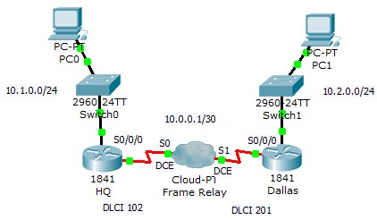
Configure the following setup in Packet Tracer
Tasks
- Drag a Generic WAN emulation cloud into the working area
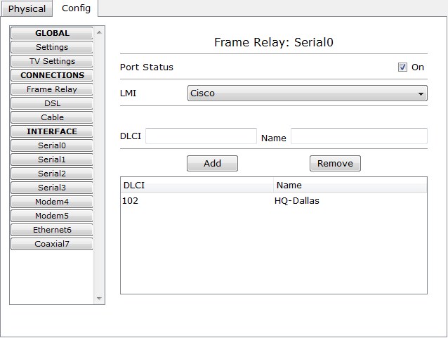
- Configure serial 0 with a DLCI of 102 and name HQ-Dallas
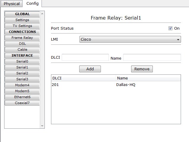
- Configure serial 1 with a DLCI of 201 and name Dallas-HW
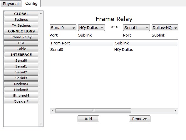
- Create a Frame Relay mapping as shown in Fig. 4
- Connect the Routers and end devices in Cisco Packet Tracer as shown in the topology
- Configure hostname and basic setup on all routers.
- Configure IP addresses and DLCIs on the serial connections
- HQ Router should use the first usable IP address in the range
- Dallas Router should have the last usable IP address in the range
- Configure the correct DLCI with the frame-relay interface-dlci <DLCI> command
What LMI protocol is used on the Serial connection?
Are the 2 routers able to ping each other?
- Configure the LAN interface with the first usable IP address in the range
- Configure the hosts with the last usable IP address in the range.
- Configure OSPF on the 2 Routers(remember to configure the FR interface for OSPF broadcast <ip ospf network broadcast>)
- Disable LMI and create static Frame Relay maps
Is Routing working as expected?
- Use some of the show commands you know to verify Frame Relay connectivity
Extra Task
- Connect another brance to the framerelay cloud
- Configure FrameRelay to be a full-mesh topology.
- Configure Sub-interfaces instead of multipoint connections


