From Teknologisk videncenter
STP
Redundant Layer 2 Topologies
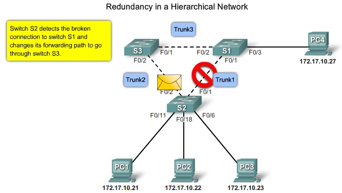
Redundancy
 Simple network VLAN mangement |
|
|
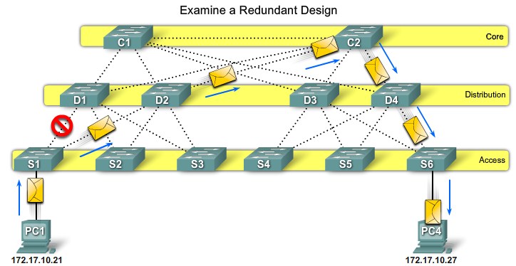 Path Failure - Access to Distribution |
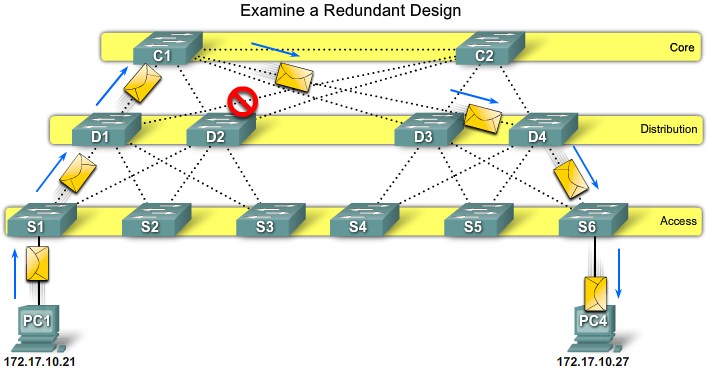 Path Failure - Distribution to Core |
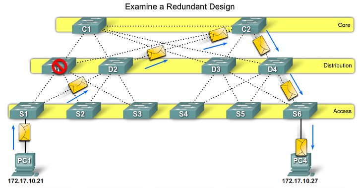 Switch Failure - Distribution layer |
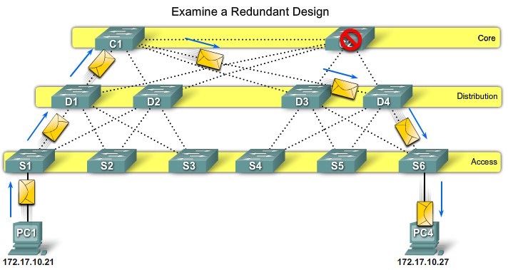 Switch Failure - Core layer |
Issues with Redundancy
|
|
|
|
Real-world Redundancy Issues
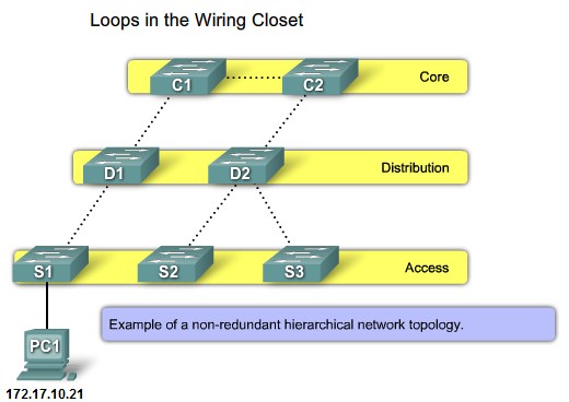 Non-Redundant network topology |
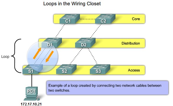 Loops from 2 connections in the same switch |
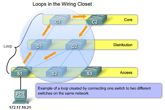 Loops from connections to a second switch |
|
|
Introduction to STP
The Spanning Tree Algorithm
|
|
|
|
|
|
|
Root ports - Switch ports closest to the root bridge.
Designated ports - All non-root ports that are still permitted to forward traffic on the network.
Non-designated ports - All ports configured to be in a blocking state to prevent loops.
|
|
|
|
|
|
|
|
|
|
|
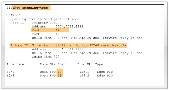 Verify port and path costs |
STP BPDU
|
|
|
Version - The version field indicates the version of the protocol, This field contains the value zero.
Message type - The message type field indicated the type of message, this field contains the value zero.
Flags - The flags field includes one of the following: Topology change(TC) bit, which signals a topology change in the event a path to the root bridge has been disrupted. Topology change acknowledgment(TCA) bit, which is set to acknowledge receipt of a configuration messege with the TC bit set.
Root ID - The Root ID field indicates the root bridge by listing its 2-byte prority followed by its 6-byte MAC address ID.
Bridge ID - The Bridge ID field indicates the priority and MAC address ID of the bridge sending the message
Port ID - The Port ID field indicates the port number from which the configuration message was sent.
Forward Delay - The Forward delay field indicates the length of time that bridges should wait before transitioning to a new state after topology change.
|
|
|
|
|
|
|
|
|
|
|
|
|
|
|
|
|
|
|
|
|
Bridge ID
|
|
|
|
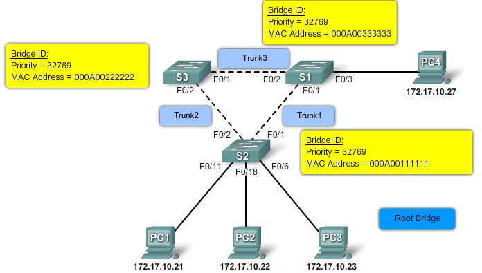 MAC Address-based desicions |
|
|
|
|
Port Roles
- Root Port
- The root port exists on non-root bridges and is the switch port with the best path to the root bridge.
- Designated Port
- The designated port exists on root and non-root bridges. For root bridges, all switch ports are designated ports. Only one designated port is allowed per segment. Designated ports are capable of populating the MAC table.
- Non-designated Port
- The non-designated port is a switch port that is blocked, so it is not forwarding data frames and not populating the MAC address table with source addresses.
- Disabled Port
- The disabled port is a switch port that is administratively shut down.
|
|
|
|
|
|
 Verify Port Roles and Priority |
STP Port States and BPDU Timers
Port States:
- Blocking
- The port is a non-designated port and does not participate in frame forwarding. The port receives BPDU frames to determine the location and root ID of the root bridge switch and what port roles each switch port should assume in the final active STP topology.
- Listening
- STP has determined that the port can participate in frame forwarding according to the BPDU frames that the switch has received thus far. At this point, the switch port is not only receiving BPDU frames, it is also transmitting its own BPDU frames and informing adjacent switches that the switch port is preparing to participate in the active topology.
- Learning
- The port prepares to participate in frame forwarding and begins to populate the MAC address table.
- Forwarding
- The port is considered part of the active topology and forwards frames and also sends and receives BPDU frames.
- Disabled
- The Layer 2 port does not participate in spanning tree and does not forward frames. The disabled state is set when the switch port is administratively disabled.
|
|
|
|
|
|
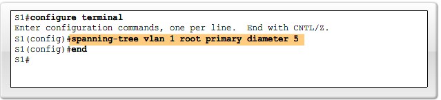 Configure network diameter |
PortFast
| PortFast is a Cisco technology. When a switch port configured with PortFast is configured as an access port, that port transitions from blocking to forwarding state immediately, bypassing the typical STP listening and learning states.
|
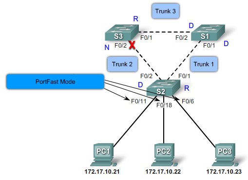 Cisco Portfast technology |
|
|
|
|
STP Convergence
STP Convergence
|
|
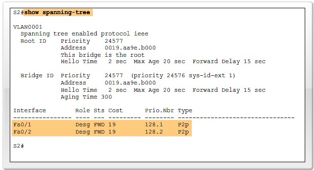
Step 1. Electing A Root Bridge
|
|
Step 2. Elect Root Ports
|
|
|
|
|
|
|
|
Step 3. Electing Desgnated Ports and Non-Designated Ports
|
|
|
|
|
|
|
|
|
|
|
|
|
|
STP Topology Change
|
|
| Topology change notification(TCN) messages are flooded out the root port, until it reaches the root bridge.
|
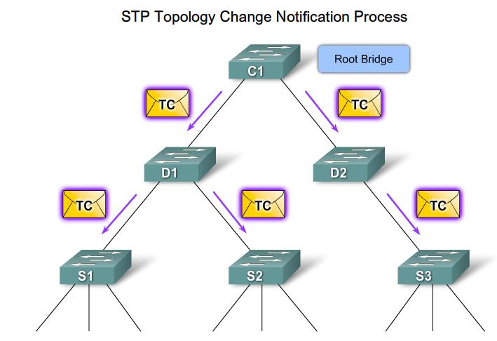 STP Broadcast notification |
| The Root Bridge broadcasts Topology change messages
|
PVST+, RSTP and Rapid-PVST+
Cisco and STP Variants
|
|
PVST+
|
|
|
|
|
|
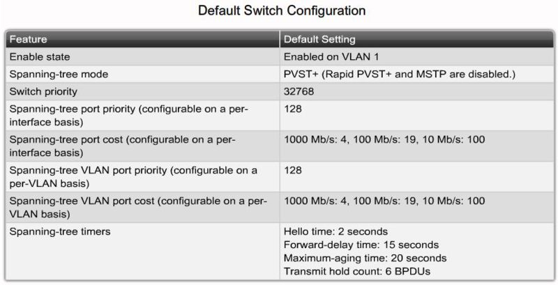 Default PVST+ configuration |
|
|
|
|
|
|
|
|
RSTP
|
|
|
|
|
|
Edge Ports
|
|
Link Types
|
|
|
Point-to-point Link Type - Links attaches to switch ports that are operating in full-duplex mode
Shared Link Type - This link is attached to a port that is operating in half-duplex mode
|
RSTP Port States and Port Roles
|
|
|
|
|
|
|
|
Configure Rapid-PVST+
|
|
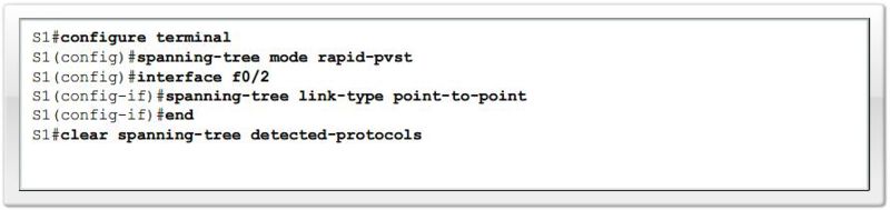 Rapid-PVST+ Example configuration |
|
|
Design STP for Trouble Avoidance
|
|
|
|
|
|
|
|
Troubleshoot STP Operation
|
|
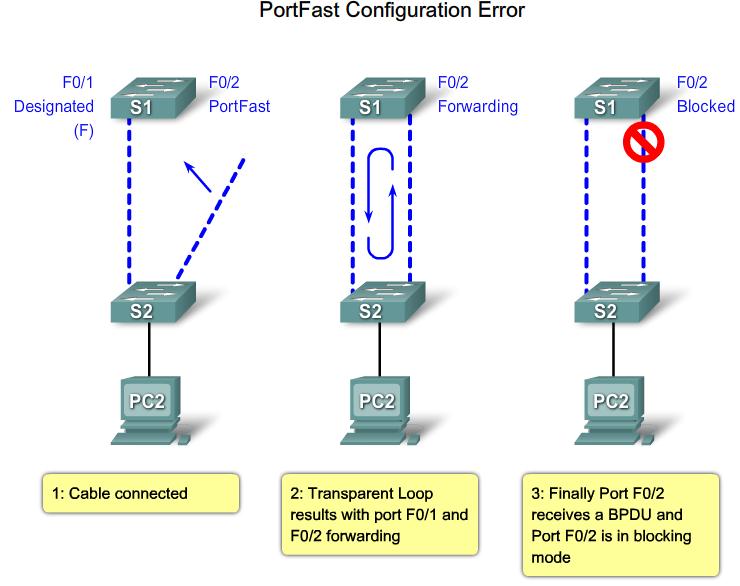 PortFast configuration error |
|
|
Chapter Summary
|
|
|
|
|
|
|
|
|
|
|
|
|
|
|
|
|
|
|
|


