From Teknologisk videncenter
Implementing Best Practices for VLAN Topologies
Describing Issues in a Poorly Designed network
Grouping Business Functions into VLANs
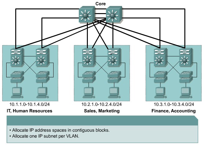 Scalable Network Addressing |
Interconnection Technologies
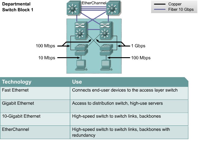 Interonnection Technologies |
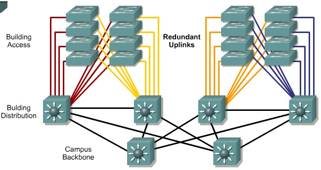
Oversubscription
- Access to distribution layer links: The oversubscription ratio should be no higher than 20:1. That is, the link can be 1/20 of the total bandwidth available cumulatively to all end devices using that link.
- Distribution to core links: The oversubscription ratio should be no higher than 4:1.
- Between core devices: There should be little to no oversubscription planning. That is, the links between core devices should be able to carry traffic at the speed represented by the aggregate number bandwidth of all the distribution uplinks into the core.
|
Network traffic Types
Describing End-to-End VLANs
Describing Local VLANs
 Local VLANs a genneraly confined to a wiring closet |
- Local VLANs should be created with physical boundaries rather than the job functions of the users on the end devices.
- Traffic from a local VLAN is routed to reach destinations on other networks.
- A single VLAN does not extend beyond the Building Distribution submodule.
|
Mapping VLANs in a Hierarchical network
|
|
When mapping VLANs onto the new hierarchical network design, keep these parameters in mind.
- Examine the subnetting scheme that has been applied to the network and associate a VLAN to each subnet.
- Configure routing between VLANs at the distribution layer using multilayer switches.
- Make end-user VLANs and subnets local to a specific switch block.
- Ideally, limit a VLAN to one access switch or switch stack. However, it may be necessary to extend a VLAN across multiple access switches within a switch block to support a capability such as wireless mobility.
|
Implementing VLANs
VLAN Configuration modes
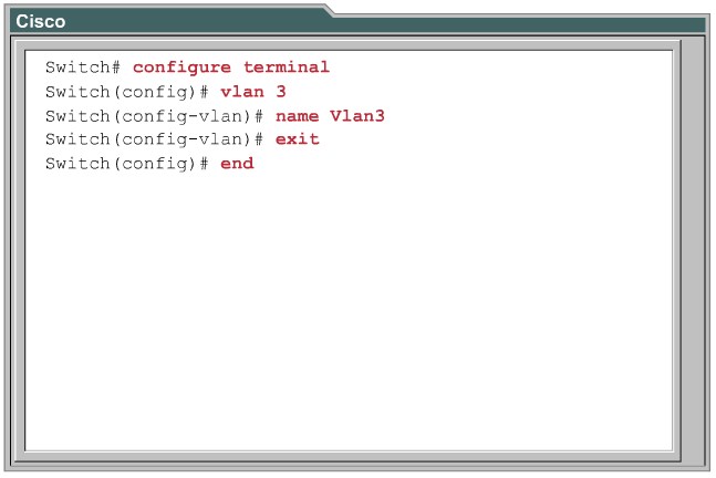 Global VLAN configuration mode |
|
|
Explaining VLAN access Ports
|
|
| VMPS - VLAN Membership Policy Server
|
Vlan Implementation
Implementing Trunks
Explaining VLAN Trunks
Describing ISL Trunks
Describing 802.1Q Trunking
Explaining 802.1Q Nativ VLANs
DTP Switchport Interactions
Configuring a Trunk
Propagating VLAN Configurations with VLAN Trunking Protocol
Explaining VTP Domains
Describing VTP
VTP Modes
Describing VTP Pruning
Describing VTP Operation
VTP Advertisements:
VTP Configuration
|
|
|
|
|
Step 1 Establish a design specifying which switches are server, client, or transparent, and what the boundaries are for the VTP domain.
Step 2 Verify the current VLAN information on any switch that will be configured as server.
Step 3 Specify the VTP password (optional).
Step 4 Specify the version number, if other than the default.
Step 5 Specify the VTP domain name (case-sensitive).
Step 6 Configure the VTP mode.
Step 7 Verify the configuration.
Step 8 Verify that updates are being sent from or received by the switch as intended.
|
Correcting Common VLAN Configuration Errors
Describing Issues with 802.1Q Native VLAN
Adding New Switches to an Existing VTP Domain
Describing Trunk Link Problems
Common Problems with VTP Configuration


