From Teknologisk videncenter
Describing STP
Identifying Traffic Loops
Describing the 802.1D Spanning Tree Protocol
Describing the Root Bridge
Describing Port Roles
Explaining Enhancements to STP
Implementing RSTP
Describing the Rapid Spanning Tree Protocol
Describing RSTP Port States
Describing RSTP Port Roles
Explaining Edge Ports
Examining the RSTP BPDU
Identifying the RSTP Proposal and Agreement Process
|
|
- Switch A has a path to the root via switch B and switch C. A new link is then created between the root and switch A, and both ports are in designated blocking state until they receive a BPDU from their counterpart. When a designated port is in a discarding or learning state (and only in this case), it sets the proposal bit on the BPDUs it sends out. This is what happens for port P0 of the root bridge.
- Switch A sees that the proposal BPDU has a superior path cost. It blocks all non-edge designated ports other than the one over which the proposal-agreement process are occurring. This operation is called sync and prevents switches below A from causing a loop during the proposal-agreement process. Edge ports do not have to be blocked and remain unchanged during sync.
- Bridge A sends an agreement that allows the root bridge to put root port P0 in forwarding state. Port P1 becomes the root port for A.
|
Describing Rapid PVST+ Implementation
Implementing MSTP
Explaining MSTP
MST Regions
Describing the Extended System ID
Configure MST
Configuring Link Aggregation with EtherChannel
Describing EtherChannel
Guidelines and restrictions when configuring EtherChannel interfaces
Configuring Load Balancing over EtherChannel
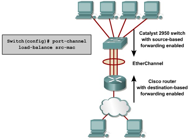 EtherChannel Load Balancing |
- src-mac: Source MAC address
- dst-mac: Destination MAC address
- src-dst-mac: Source and destination MAC addresses
- src-ip: Source IP address
- dst-ip: Destination IP address
- src-dst-ip: Source and destination IP addresses (default)
- src-port: Source TCP/User Datagram Protocol (UDP) port
- dst-port: Destination TCP/UDP port
- src-dst-port: Source and destination TCP/UDP ports
|
Summary


