IP Multicast
Se også IP Multicast Design
Architecture
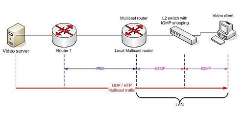
A network designed to deliver a multicast service (like video) using IGMP might use this basic architecture:
IGMP is used both by the client computer and the adjacent network switches to connect the client to a local multicast router. Protocol Independent Multicast (PIM) is then used between the local and remote multicast routers, to direct multicast traffic from the video server to many multicast clients.
Multicast Applications
One-to-Many
where one sender sends data to many receivers.
- This type of application may be used for audio or video distribution, push media, announcements, monitoring, and so on.
- If a one-to-many application needs feedback from receivers, it becomes a many-to-many application
Many-to-Many
where a host can be a sender and a receiver simultaneously or where two or more receivers also act as senders.
- Receiving data from several sources increases the complexity of applications and creates different management challenges.
- Using a many-to-many multicast concept as a foundation, a whole new range of applications may be built (for example, collaboration, concurrent processing, and distributed interactive simulations).
Many-to-One
where many receivers are sending data back to one sender.
- Used by financial applications and networks. Other uses include resource discovery, data collection, auctions, and polling.
IP multicast Addresses
IP Multicast addresses IP Class D ranging from from 224.0.0.0 to 239.255.255.255 are divided into three multicast address groups.
| From | to | Range |
|---|---|---|
| 224.0.0.0 | 224.0.0.255 | Reserved link, Local addresses |
| 224.0.1.0 | 238.255.255.255 | Globally scoped addresses |
| 239.0.0.0 | 239.255.255.255 | Limited Scope addresses |
Locally scoped (reserved link local) addresses
- Reserved by the Internet Assigned Numbers Authority (IANA) for network protocol use.
- Address range is from 224.0.0.0 through 224.0.0.255.
- Multicasts in this range are never forwarded off the local network, regardless of Time to Live (TTL). Usually, the TTL is set to 1.
| Address | Meaning |
|---|---|
| 224.0.0.1 | All multicast Systems on a subnet |
| 224.0.0.2 | All multicast Routers on a subnet |
| 224.0.0.4 | All Distant vector multicast routing protocol routers |
| 224.0.0.5 | All OSPF Routers |
| 224.0.0.6 | All OSPF designated Routers |
| 224.0.0.9 | All RIPv2 Routers |
| 224.0.0.10 | All EIGRP Routers |
| 224.0.0.13 | All PIMv2 Routers |
| 224.0.0.18 | Virtual Router Redundancy Protocol |
| 224.0.0.22 | IGMP Version 3 (Internet Group Management Protocol) |
| 224.0.0.102 | Hot Standby Router Protocol Version 2 |
| 224.0.0.251 | Multicast DNS address |
| 224.0.1.41 | H.323 Gatekeeper discovery address |
Globally scoped addresses
- Allocated dynamically throughout the Internet.
- Address range is from 224.0.1.0 through 238.255.255.255.
- The 224.2.X.X range is used in Multicast Backbone (Mbone) applications. Established by the Internet Engineering Task Force (IETF) to multicast audio and video meetings, Mbone is a collection of Internet routers that support IP multicasting on which various public and private audio and video programs are sent.
GLOP Multicast Block
This block of addresses has been assigned by the IANA as an experimental, statically assigned range of multicast addresses intended for use by Content Providers, ISPs, or anyone wishing to source content into the global Internet. This allocation methodology, called GLOP addressing, which is defined in RFC 2770, uses the multicast group range of 233.0.0.0 through 233.255.255.255 (233/8) and provides each Autonomous System with a block of 255 statically assigned multicast addresses. Content providers who wish to transmit multicast traffic to their customers in the Internet and that have an assigned Autonomous System Number (ASN) can use multicast addresses from their block of 255 static GLOP addresses to transmit content. If the content provider does not have its own assigned ASN, usually it can lease static GLOP addresses from their Internet Service Provider.
GLOP Example
The GLOP IPv4 address is built in octet two and three from the providers BGP AS number.
| Octet 1 | Octet 2 and 3 | octet 4 |
|---|---|---|
| 233 | AS NUMBER | Local bits |
tdc has BGP AS 3292 - two octet AS number necessary. Converting 3292 to binary gives 110011011100 seperate it to two binary octets 00001100 11011100 and converting each octet separately to decimal gives 12 and 220, giving tdc the GLOP addresses 233.12.220.x, where x defines locally assigned bits.
Limited (administratively) scoped addresses
- Reserved for use inside private domains. Similar to the private IP address space that is used within the boundaries of a single organization, limited or administratively scoped addresses are constrained to a local group or organization.
- Address range is from 239.0.0.0 through 239.255.255.255. rfc3180 Glob addressing
- Organizations can use limited scope addresses to have local multicast applications that will not be forwarded over the Internet.
- Within an autonomous system or domain, the limited scope address range can be further subdivided so that local multicast boundaries can be defined. This subdivision is called address scoping and allows for address reuse between smaller domains. The administratively scoped multicast address space is divided into the following scopes:
Site local Scope
- 239.252.0.0/16
- 239.253.0.0/16
- 239.254.0.0/16
- 239.255.0.0/16
Organizational Local Scope
- 239.192.0.0 to 239.251.255.255
Enterprise internal group address assignment
The Muticast Address Dynamic Client Alocation Protocol(MADCAP) allows a client workstation to "lease" a miulticast address from a MADCAP server in a manner similar to how a workstation can "lease" an IP address from a DHCP server.
Layer 2 Multicast addressing
IP Multicast MAC address mapping on Ethernet
On Ethernet the IP multicast address is converted to a Ethernet Multicast address.
- IPv4 addresses are 32 bits wide.
- Ethernet MAC Addresses are 48 bits wide.
Because the IP address are shorter than the MAC address a direct conversion is not possible.
How does a router or a switch relate a multicast IP address with a MAC address? Normally, network interface cards (NICs) on a LAN segment only receive packets destined for their burned-in MAC address. However, there is no Address Resolution Protocol (ARP) equivalent for multicast address mapping.
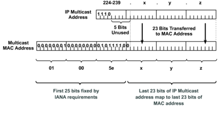
Instead, IANA has set aside the vendor code portion of the reserved Organizationally Unique Identifier (OUI) value to identify multicast MAC addresses. Multicast MAC addresses always begin with the low-order bit (0x01) in the first octet. Specifically, the 0x01005e prefix (plus the next lower bit, which is zero) has been reserved for mapping Layer 3 IP multicast addresses into Layer 2 MAC addresses. The complete multicast MAC address range is from 0100.5e00.0000 through 0100.5e7f.ffff.
This makes the first 25 bits of the MAC address fixed (24 bits plus the zero bit) and allows for the last 23 bits of the MAC address to correspond to the last 23 bits in the IP multicast group address. The translation between IP multicast and MAC address is achieved by the mapping of the low-order 23 bits of the IP (Layer 3) multicast address into the low-order 23 bits of the IEEE (Layer 2) MAC address.
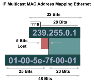
There are 28 bits of unique address space for an IP multicast address (32 minus the first four bits containing the 1110 Class D prefix), and there are only 23 bits mapped into the IEEE MAC address. Therefore, five bits of the IP address are unused and not transferred into the MAC address, which means that there are five bits of overlap.
The result is that two (or more) different IP multicast addresses may map to the same MAC multicast address. For example, 224.1.1.1 and 225.1.1.1 map to the same multicast MAC address. If one user subscribed to Group A (as designated by 224.1.1.1) and the other user subscribed to Group B (as designated by 225.1.1.1), they would both receive both A and B streams at Layer 2. At Layer 3, however, only the packets associated with the IP address of the selected multicast group would be viewable, because the port ranges used within the address is different between aliased streams.
This gives the possibility that 32 different multicast IP addresses could all correspond to a single multicast MAC address. For example, all the IP multicast addresses in Figure map to the same Layer 2 multicast of 01-00-5e-0a-00-01.
Network administrators should consider this when assigning IP multicast addresses.
IGMP
Internet Group Management Protocol (IGMP)
IGMP is a host-to-router protocol used when hosts want to join a multicast group. With IGMPv1, routers send periodic membership queries to the multicast address 224.0.0.1. Hosts send membership reports to the group multicast address they want to join. Hosts silently leave the multicast group.
- IGMP has evolved through three versions (1, 2, and 3).
- Understanding this protocol is fundamental in defining the multicast group membership join and leave process, which is a required function of multicasting.
IGMP Version 1
RFC 1112, Host Extensions for IP Multicasting, describes the specification for IGMP Version 1 (IGMPv1). A diagram of the packet format for an IGMPv1 message is shown in Figure 5. Figure 5 IGMPv1 Message Format In Version 1, only the following two types of IGMP messages exist:
- Membership query
- Membership report
| + | Bits 0 - 3 | 4 - 7 | 8 - 15 | 16 - 23 | 24 - 31 | |||||||||||||||||||||||||||||||||||
|---|---|---|---|---|---|---|---|---|---|---|---|---|---|---|---|---|---|---|---|---|---|---|---|---|---|---|---|---|---|---|---|---|---|---|---|---|---|---|---|---|
| 0 | Version | Type | Unused | Checksum | ||||||||||||||||||||||||||||||||||||
| 32 | Group Address | |||||||||||||||||||||||||||||||||||||||
Hosts send out IGMP membership reports corresponding to a particular multicast group to indicate that they are interested in joining that group. The TCP/IP stack running on a host automatically sends the IGMP Membership report when an application opens a multicast socket. The router periodically sends out an IGMP membership query to verify that at least one host on the subnet is still interested in receiving traffic directed to that group. When there is no reply to three consecutive IGMP membership queries, the router times out the group and stops forwarding traffic directed toward that group.
IGMP Version 2
IGMPv1 has been superceded by IGMP Version 2 (IGMPv2), which is now the current standard.
IGMPv2 is backward compatible with IGMPv1. RFC 2236, Internet Group Management Protocol,
Version 2, describes the specification for IGMPv2. A diagram of the packet format for an IGMPv2
In Version 2, the following four types of IGMP messages exist:
- Membership query
- Version 1 membership report
- Version 2 membership report
- Leave group
| + | Bits 0 - 7 | 8 - 15 | 16 - 23 | 24 - 31 | ||||||||||||||||||||||||||||
|---|---|---|---|---|---|---|---|---|---|---|---|---|---|---|---|---|---|---|---|---|---|---|---|---|---|---|---|---|---|---|---|---|
| 0 | Type | Max Resp Time | Checksum | |||||||||||||||||||||||||||||
| 32 | Group Address | |||||||||||||||||||||||||||||||
IGMP Version 2 works basically the same way as Version 1. The main difference is that there is a leave group message. With this message, the hosts can actively communicate to the local multicast router that they intend to leave the group. The router then sends out a group-specific query and determines if any remaining hosts are interested in receiving the traffic. If there are no replies, the router times out the group and stops forwarding the traffic. The addition of the leave group message in IGMP Version 2 greatly reduces the leave latency compared to IGMP Version 1. Unwanted and unnecessary traffic can be stopped much sooner.
IGMP Version 3
IGMP Version 3 (IGMPv3) is the next step in the evolution of IGMP. IGMPv3 adds support for “source filtering,” which enables a multicast receiver host to signal to a router the groups from which it wants to receive multicast traffic, and from which sources this traffic is expected. This membership information enables Cisco IOS software to forward traffic from only those sources from which receivers requested the traffic. IGMPv3 is an emerging standard. The latest versions of Windows, Macintosh, and UNIX operating systems all support IGMPv3. At the time this document was being written, application developers were in the process of porting their applications to the IGMPv3 API.
Defined by RFC 3376| Bits 0 - 7 | 8 - 15 | 16 - 23 | 24 - 31 | ||||||||||||||||||||||||||||
|---|---|---|---|---|---|---|---|---|---|---|---|---|---|---|---|---|---|---|---|---|---|---|---|---|---|---|---|---|---|---|---|
| Type | Max Resp Time | Checksum | |||||||||||||||||||||||||||||
| Group Address | |||||||||||||||||||||||||||||||
| S | QRV | QQIC | Number of sources N | ||||||||||||||||||||||||||||
| Source address 1 | |||||||||||||||||||||||||||||||
| Source address 2 | |||||||||||||||||||||||||||||||
| ... | |||||||||||||||||||||||||||||||
| Source address N | |||||||||||||||||||||||||||||||
Multicast traffic considerations
When using multicast through Layer 2 Switche - Access layer - the Layer 2 Swithes can flood the trafic to all ports. To avoid this you can use IGMP snooping or CGMP (Cisco proprietary protocol) to limit traffic to only those hosts who join the multicast group.
IGMP Snooping
IGMP snooping allows a switch to identify end systems that request multicast traffic and limit forwarding of a multicast address to specific ports. IGMP snooping is enabled by default, and can be manually enabled by the command ip igmp snooping. You can use the show multicast group and show multicast router commands to display the learned groups and associated router ports.
Example Cisco IOS
Switch2#<input>show ip igmp snooping vlan 1</input>
Global IGMP Snooping configuration:
-----------------------------------
IGMP snooping              : Enabled
IGMPv3 snooping (minimal)  : Enabled
Report suppression         : Enabled
TCN solicit query          : Disabled
TCN flood query count      : 2
Last Member Query Interval : 1000

Vlan 1:
--------
IGMP snooping                       : Enabled
IGMPv2 immediate leave              : Disabled
Explicit host tracking              : Enabled
Multicast router learning mode      : pim-dvmrp
Last Member Query Interval          : 1000
CGMP interoperability mode          : IGMP_ONLY
CGMP
- Cisco Group Message Protocol
CGMP is a Cisco proprietary protocol that runs between Multicast Routers and Switches. The Router informs the Switch which hosts receive the multicast stream. The switch forwards traffic only on ports where Receivers are located.


