Pederrs CCNP 1
Contents
- 1 Module 1: Scalable Network Design
- 2 Module 2: EIGRP
- 3 Module 3: OSPF
- 3.1 Forkortelser:
- 3.2 Teori
- 3.2.1 3.1.1 Link State Routing Protocols
- 3.2.2
- 3.2.3 3.1.3 Link State Data Structures
- 3.2.4 3.1.6 Types of OSPF Routers
- 3.2.5 3.1.9 Link-State Data Structures
- 3.2.6 3.2.1 OSPF Packet Types
- 3.2.7 3.2.2 OSPF Packet Header Format
- 3.2.8 3.3.4 Configuring a Router ID
- 3.2.9 Verifying the OSPF Operation
- 3.2.10 3.6.3 OSPF LSA Types (cont.)
- 4 Module 4: Integrated IS-IS
- 4.1 Forkortelser
- 4.2 Teori
- 4.2.1 4.1.2 IS-IS and OSPF
- 4.2.2 4.1.4 IS-IS Features
- 4.2.3 4.1.5 IS-IS Link-State Operation
- 4.2.4 4.1.8 The ES-IS Protocol
- 4.2.5 4.1.9 OSI Routing Levels
- 4.2.6 4.1.10 IS-IS and OSPF Network Design
- 4.2.7 4.1.11 Differences Between Integrated IS-IS and OSPF
- 4.2.8 4.2.1 NSAP Addresses
- 4.2.9 4.2.2 NSAP Address Structure
- 4.2.10 4.2.3 NSAP Address Example
- 5 Module 5: Route Optimization
- 6 Module 6: BGP
- 6.1 Forkortelser
- 6.2 Teori
- 6.2.1 6.1.2 BGP Multihoming Options
- 6.2.2 6.1.6 BGP Routing Between Autonomous Systems
- 6.2.3 6.1.7 Path-Vector Functionality
- 6.2.4 6.1.9 Features of BGP
- 6.2.5 6.1.10 BGP Databases
- 6.2.6 6.1.11 BGP Message Types
- 6.2.7 6.2.2 Establishing a Connection Between External BGP Neighbors
- 6.2.8 6.2.3 Establishing a Connection Between Internal BGP Neighbors
- 6.2.9 6.2.5 IBGP in a Nontransit Autonomous System
- 6.2.10 6.2.6 Routing Issues in a Transit Autonomous System
- 6.2.11 6.3.1 Basic BGP Configuration
- 6.2.12 6.3.2 Activate a BGP Session
- 6.2.13 6.3.3 Shutting Down a BGP Neighbor
- 6.2.14 6.3.4 BGP Configuration Considerations
- 6.2.15 6.3.5 IBGP Peering Issue
- 6.2.16 6.3.6 BGP neighbor update-source Command
- 6.2.17 6.3.7 EBGP Peering Issue (EBGP Multihop)
- 6.2.18 6.3.8 Next Hop Behavior
- 6.2.19 6.3.9 BGP neighbor next-hop-self Command
- 6.2.20 6.3.10 Injection Routing Information into BGP
- 6.2.21 6.3.12 BGP Synchronization
- 6.2.22 6.3.13 BGP Synchronization Example
- 6.2.23 6.4.1 BGP Neighbor States
- 6.2.24 6.4.5 Configuring a Peer Group Example
- 6.2.25 6.4.7 Configuring BGP Authentication
- 6.2.26 6.4.11 Soft Reset of BGP Sessions
- 6.2.27 6.5.3 AS Path Attribute
- 6.2.28 6.5.4 Next-Hop Attribute
- 6.2.29 6.5.5 Origin Attribute
- 6.2.30 6.5.6 Local Preference Attribute
- 6.2.31 6.5.7 MED Attribute
- 6.2.32 6.5.8 Weight Attribute
- 6.2.33 6.5.10 Selecting a BGP Path
- 6.2.34 6.6.3 Changing the BGP Local Preference for All Routes
- 6.2.35 6.6.7 Setting the MED with Route Maps
- 7 Module 7: IP Multicasting
- 7.1 Forkortelser
- 7.2 Teori
- 7.2.1 7.1.3 Multicast Advantages and Disadvantages
- 7.2.2 7.1.4 Multicast Applications
- 7.2.3 7.1.5 IP Multicast Addresses
- 7.2.4 7.1.6 Layer 2 Multicast Addressing
- 7.2.5 7.2.2 IGMPv2 Join Group and Leave Group Messages
- 7.2.6 7.2.3 Introducing IGMPv3
- 7.2.7 7.2.5 Multicast in the Layer 2 Switching Environment
- 7.2.8 7.2.6 Multicast in Layer 2 Solutions
- 7.2.9 7.2.7 Cisco Group Management Protocol (CGMP)
- 7.2.10 7.2.8 IGMP Snooping
- 7.2.11 7.3.1 Protocols Used in Multicast
- 7.2.12 7.3.2 Multicast Distribution Trees
- 7.2.13 7.3.3 Multicast Distribution Trees Identification
- 7.2.14 7.3.4 IP Multicast Routing
- 7.2.15 7.3.5 Protocol-Independent Multicast: Describing PIM-DM
- 7.2.16 7.3.6 Protocol-Independent Multicast: Describing PIM-SM
- 7.2.17 7.4.1 Enabling PIM Sparse Mode and Sparse-Dense Mode
- 7.2.18 7.4.2 Inspecting the Multicast Routing Table
- 7.2.19 7.4.3 Finding PIM Neighbors
- 7.2.20 7.4.4 Checking RP Information
- 7.2.21 7.4.5 Checking the Group State
- 7.2.22 7.4.6 Configuring a Router to Be a Member of a Group
- 8 Module 8: IPv6
- 8.1 Forkortelser
- 8.2 Teori
- 8.2.1 8.1.2 IPv6 Features
- 8.2.2 8.1.3 Large Address Space
- 8.2.3 8.2.1 IPv6 Addressing Architecture
- 8.2.4 8.2.2 Comparing IPv4 and IPv6 Headers
- 8.2.5 8.2.3 IPv6 Extension Headers
- 8.2.6 8.2.4 Defining Address Representation
- 8.2.7 8.2.5 IPv6 Address Types
- 8.2.8 8.2.6 IPv6 Global Unicast and Anycast Addresses
- 8.2.9 8.3.1 Defining Host Interface Addresses
- 8.2.10 8.3.2 Link Local Address
- 8.2.11 8.3.3 Stateless Autoconfiguration 8.3.4
- 8.2.12 EUI-64 to IPv6 Identifier
- 8.2.13
- 8.2.14
- 8.2.15
- 8.2.16
- 8.2.17
- 8.2.18
- 8.2.19
- 8.2.20
- 8.2.21
- 8.2.22
- 8.2.23
- 8.2.24
- 8.2.25
- 8.2.26
- 8.2.27
- 8.2.28
- 8.2.29
- 8.2.30
- 8.2.31
- 8.2.32
- 8.2.33
- 8.2.34
Module 1: Scalable Network Design
Forkortelser:
ECNM = Enterprise Composite Network Model
NAC = Network Access Control (NAC) and
IBNS = Identity Based Network Services (IBNS)
Module 2: EIGRP
Forkortelser:
AD = advertised distance (AD)
FD = feasible distance (FD)
AD og FD forklaring: The lowest cost route is calculated by adding the cost between the next-hop router and the destination—referred to as the advertised distance (AD)—to the cost between the local router and the next-hop router. The sum of these costs is called the feasible distance (FD).
DUAL = Diffusing Update Algorithm (DUAL)
PDM = Protocol-dependent modules (PDMs) are responsible for network layer protocol-specific requirements. EIGRP supports IP,AppleTalk, and Novell NetWare. Each protocol has its own EIGRP module and operates independently from any of the others that may be running.
RTP = RTP is responsible for guaranteed ordered delivery and reception of EIGRP packets to all neighbors. RTP supports intermixed transmission of multicast and unicast packets. For efficiency, only certain EIGRP packets are transmitted reliably.
SRTT = (smoothed round-trip time): Average number of milliseconds it takes for an EIGRP packet to be sent to this neighbor and for the local router to receive an acknowledgment of that packet. This timer determines the retransmit interval, also known as the retransmission timeout (RTO).
RTO = (retransmission timeout): Amount of time, in milliseconds, that the router waits for an acknowledgment before retransmitting a reliable packet from the retransmission queue to a neighbor. If an EIGRP update, query, or reply is sent, a copy of the packet is queued. If the RTO expires before an acknowledgment is received, another copy of the queued packet is sent.
SIA = stuck in active (SIA)
LSDB = link-state database (LSDB)
SPF = Shortest Path First (SPF)
Teori
Although the metric can be based on five criteria, EIGRP uses only two of these criteria by default:
- Bandwidth: Smallest bandwidth between source and destination.
- Delay: Cumulative interface delay along the path.
Three other criteria can be used, but are not recommended, because they typically result in frequent recalculation of the topology table:
- Reliability: Worst reliability between source and destination, based on keepalives.
- Loading: Worst load on a link between source and destination, based on the packet rate and the configured bandwidth of the interface.
- MTU: Smallest MTU in the path. MTU is included in the EIGRP routing update, but is not actually used in the metric calculation.
Module 3: OSPF
Forkortelser:
Teori
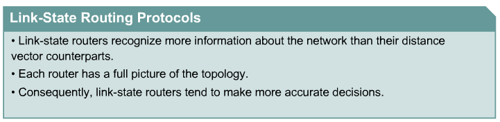
3.1.1 Link State Routing Protocols
3.1.3 Link State Data Structures

3.1.6 Types of OSPF Routers
The four different types of OSPF routers are:
- Internal routers: Routers that have all their interfaces in the same area and have identical LSDBs.
- Backbone routers: Routers that sit on the perimeter of the backbone area and have at least one interface connected to area 0. Backbone routers maintain OSPF routing information using the same procedures and algorithms as internal routers.
- Area border routers: Routers that have interfaces attached to multiple areas, maintain separate LSDBs for each area to which they connect, and route traffic destined to or arriving from other areas. Area border routers (ABRs) are exit points for the area, which means that routing information destined for another area can get there only via the ABR of the local area. ABRs can be configured to summarize the routing information from the LSDBs of their attached areas. ABRs distribute the routing information into the backbone. The backbone routers then forward the information to the other ABRs. In a multiarea network, an area can have one or more ABRs.
- Autonomous System Boundary Routers: Routers that have at least one interface attached to an external internetwork (another autonomous system), such as a non-OSPF network. Autonomous system boundary routers (ASBRs) can import non-OSPF network information to the OSPF network and vice versa; this process is called route redistribution.

3.1.9 Link-State Data Structures
When each router receives the LSU, it does the following:
- If the LSA does not already exist, the router adds the entry to its LSDB, sends a link-state acknowledgment (LSAck) back, floods the information to other routers, runs SPF, and updates its routing table.
- If the entry already exists and the received LSA has the same sequence number, the router ignores the LSA entry.
- If the entry already exists but the LSA includes newer information (it has a higher sequence number), the router adds the entry to its LSDB, sends an LSAck back, floods the information to other routers, runs SPF, and updates its routing table.
- If the entry already exists but the LSA includes older information, it sends an LSU to the sender with its newer information

3.2.1 OSPF Packet Types
The OSPF protocol exchanges five packet types:
- Hello
- Database description (DBD)
- Link-state request (LSR)
- Link-state update (LSU)
- Link-state acknowledgement (LSAck)

3.2.2 OSPF Packet Header Format
All five OSPF packets are encapsulated directly into an IP payload, as shown in Figure . The OSPF packet does not use TCP or User Datagram Protocol (UDP). OSPF requires a reliable packet transport scheme. Since TCP is not used, it has defined its own acknowledgment routine that uses an acknowledgment packet (OSPF packet type 5).
In the IP header, a protocol identifier of 89 defines all OSPF packets. Each of the OSPF packets begins with the same header format. This header has the following fields:
- Version number: For OSPF version 2 or 3
- Type: Differentiates the five OSPF packet types
- Packet length: Length of packet in bytes
- Router ID: Defines which router is the source of the packet
- Area ID: Defines the area where the packet originated
- Checksum: Used for packet-header error detection to ensure that the OSPF packet was not corrupted during transmission
- Authentication type: An option that specifies either no authentication, clear-text passwords, or encrypted Message Digest 5 (MD5) formats for router authentication
- Authentication: Used in the authentication scheme
- Data (for hello packet): Includes a list of known neighborsData (for DBD packet): Contains a summary of LSDB, which includes all known router *IDs and their last sequence number, among a number of other fields
- Data (for LSR packet): Contains the type of LSU needed and the router ID that has the needed LSU
- Data (for LSU packet): Contains the full LSA entries; multiple LSA entries can fit in one OSPF update packet
- Data (for LSAck packet): Is empty

3.3.4 Configuring a Router ID

Verifying the OSPF Operation

3.6.3 OSPF LSA Types (cont.)
Type 1 Every router generates router link advertisements for each area to which it belongs. A type 1 LSA describes the collective states of the directly connected links (interfaces) of the router. These LSAs are flooded only within the area in which they are originated.
Type 2 A type 2 LSA is generated for every transit broadcast and NBMA network within an area. A transit network has at least two directly attached OSPF routers. Ethernet is an example of a transit network.
The DR of the network is responsible for advertising the network LSA. A type 2 network LSA lists each of the attached routers that make up the transit network, including the DR itself, as well as the subnet mask used on the link. The type 2 LSA then floods to all routers within the transit network area. Type 2 LSAs never cross an area boundary. The link-state ID for a network LSA is the IP interface address of the DR that advertises it.
Type 3 The ABR sends type 3 summary LSAs. Type 3 LSAs advertise any networks owned by an area to the rest of the areas in the OSPF autonomous system, as shown in Figure .
The link-state ID is set to the network number; the mask is also advertised.
By default, OSPF does not automatically summarize groups of contiguous subnets or summarize a network to its classful boundary. The network operator uses configuration commands to specify how the summarization occurs. By default, a type 3 LSA is advertised into the backbone area for every subnet defined in the originating area, which can cause significant flooding problems. Consequently, you should always consider using manual route summarization at the ABR.
Summary LSAs are flooded throughout a single area only, but are regenerated by ABRs to flood into other areas.
Note By default, summary LSAs do not contain summarized routes.
Type 4
A type 4 summary LSA is generated by an ABR only when an ASBR exists within an area. A type 4 LSA identifies the ASBR and provides a route to it. The link-state ID is set to the ASBR router ID. All traffic destined to an external autonomous system requires routing table knowledge of the ASBR that originated the external routes.
In Figure , the ASBR sends a type 1 router LSA with an external bit (e bit) that is set to identify itself as an ASBR. When the ABR, which is identified with a border bit (b bit) in the router LSA, receives the type 1 LSA, it builds a type 4 LSA and floods it to the backbone (area 0). Subsequent ABRs regenerate a type 4 LSA to flood into their areas.
Type 5 Type 5 external LSAs describe routes to networks outside the OSPF autonomous system. Type 5 LSAs are originated by the ASBR and are flooded to the entire autonomous system.
The link-state ID is the external network number. Because of the flooding scope, and depending on the number of external networks, the default lack of route summarization can be a major issue with external LSAs. Therefore, you should summarize blocks of external network numbers at the ASBR to reduce flooding problems.
Type 6 Type 6 LSAs are specialized LSAs that are used in multicast OSPF applications.
Type 7 Type 7 is an LSA type that is used in not-so-stubby areas (NSSAs). They are originated by ASBRs within NSSAs and are flooded only within the NSSA in which they originated.
Type 8 Type 8 is a specialized LSA that is used in internetworking OSPF and Border Gateway Protocol (BGP).
Types 9, 10, and 11 The opaque LSAs, types 9, 10, and 11, are designated for future upgrades to OSPF for application-specific purposes. For example, Cisco Systems uses opaque LSAs for Multiprotocol Label Switching (MPLS) with OSPF. Opaque LSAs are distributed using standard LSDB flooding mechanisms. Each type has a different flooding scope.
Standard area: Accepts link updates, route summaries, and external routes (the default).
Backbone area (transit area): The central entity to which all other areas connect to exchange and route information. The backbone area is labeled area 0. The OSPF backbone includes all the properties of a standard OSPF area.
Stub area: Does not accept information about routes external to the autonomous system, such as routes from non-OSPF sources. This means that no type 5 LSAs are known inside the area, and consequently type 4 LSAs are unnecessary. Type 4 and 5 LSAs are blocked.
ABRs at the edge of the stub area use type 3 LSAs to advertise a single default route (0.0.0.0) into the area. If routers need to route to networks outside the autonomous area, they use the default route.
Stub areas cannot contain ASBRs (except that the ABRs may also be ASBRs).
Totally stubby area: Does not accept external autonomous system routes or summary routes from other areas internal to the autonomous system. The ABR of the totally stubby area blocks type 4 and 5 LSAs as well as all summary LSAs (type 3), with an exception of a single type 3 LSA to advertise the default route.
The default route advertised by the ABR is used to reach destinations external to the autonomous system and all destinations external to the area. Therefore, if the router needs to send a packet to a network external to the area, it sends the packet using a default route.
Totally stubby areas cannot contain ASBRs (except that the ABRs may also be ASBRs).
Not-so-stubby area: An NSSA is an addendum to the OSPF RFC. It offers benefits that are similar to those of a stub or totally stubby area, but also allows external routes to be advertised into the OSPF autonomous system. Therefore, NSSAs allow ASBRs, which is against the rule in a stub area.
The ASBR originates type 7 LSAs to advertise the external destinations. The type 7 LSAs are flooded throughout the NSSA but are blocked by the ABR. The ABR converts the type 7 LSA into a type 5 LSA, which is then propagated through the remainder of the autonomous system.
Module 4: Integrated IS-IS
Forkortelser
MPLS/TE = Multiprotocol Label Switching Traffic Engineering (MPLS/TE).
IGP = interior gateway protocol (IGP)
CLNS = Connectionless Network Service (CLNS)
CLNP = Connectionless Network Protocol (CLNP)
LSP = link-state packet (LSP)
PDU = protocol data unit (PDU)
IS = Intermediate System
ES = end system (ES)
ES-IS = End System-to-Intermediate System (ES-IS)
ESH = End System Hello (ESH)
ISH = Intermediate System Hello (ISH)
IIH = IS-IS Hello (IIH)
DIS = designated IS router (DIS)
NSAP = network service access points (NSAP)
NSEL = NSAP selector (NSEL)
IDP = initial domain part (IDP)
AFI = authority and format identifier (AFI)
IDI = initial domain identifier (IDI)
DSP = domain specific part (DSP)
HO-DSP = high-order DSP (HO-DSP)
SNPA = subnetwork point of attachment (SNPA)
CLV = Code, Length, Value (CLV)
SNP = Sequence number PDU (SNP)
PRC = partial route calculation (PRC)
Example of a net address:
For example, you might assign 49.0001.0000.0c12.3456.00, which represents the following:
AFI of 49
Area ID of 0001
System ID of 0000.0c12.3456, the MAC address of a LAN interface
NSEL of 0
Teori
4.1.2 IS-IS and OSPF

4.1.4 IS-IS Features

4.1.5 IS-IS Link-State Operation

4.1.8 The ES-IS Protocol

4.1.9 OSI Routing Levels

4.1.10 IS-IS and OSPF Network Design

4.1.11 Differences Between Integrated IS-IS and OSPF

4.2.1 NSAP Addresses

4.2.2 NSAP Address Structure

4.2.3 NSAP Address Example

Module 5: Route Optimization
Forkortelser
PBR = Policy-based routing (PBR)
Teori
5.1.4 Using Seed Metrics

5.1.6 Defining Administrative Distance

5.3.2 Passive Interfaces

5.4.1 Defining Route Maps

5.4.3 Route Map Operation


5.4.4 Using Route Map Commands

5.5.3 Configuring DHCP

Module 6: BGP
Forkortelser
Protocols that run inside an enterprise are called interior gateway protocols (IGPs). Examples of IGPs include RIP versions 1 and 2, EIGRP, and OSPF.
Protocols that run outside an enterprise, or between autonomous systems, are called exterior gateway protocols (EGPs). Typically, EGPs are used to exchange routing information between Internet Service Providers (ISPs).
IGP: Exchanges routing information within an autonomous system. RIP, IGRP, OSPF, IS-IS, and EIGRP are IGPs.
EGP: Exchanges routing information between different autonomous systems. BGP is an EGP.
IDRP = BGP is an interdomain routing protocol (IDRP), also known as an EGP.
EBGP = When BGP is running between routers in different autonomous systems, it is called External BGP (EBGP).
IBGP = When BGP is running between routers in the same autonomous system, it is called Internal BGP (IBGP).
RIR = Regional Internet Registry (RIR)
FSM = finite-state machine (FSM)
Teori
6.1.2 BGP Multihoming Options

6.1.6 BGP Routing Between Autonomous Systems

6.1.7 Path-Vector Functionality

6.1.9 Features of BGP

6.1.10 BGP Databases

6.1.11 BGP Message Types

6.2.2 Establishing a Connection Between External BGP Neighbors

6.2.3 Establishing a Connection Between Internal BGP Neighbors

6.2.5 IBGP in a Nontransit Autonomous System

6.2.6 Routing Issues in a Transit Autonomous System

6.3.1 Basic BGP Configuration

6.3.2 Activate a BGP Session

6.3.3 Shutting Down a BGP Neighbor

6.3.4 BGP Configuration Considerations

6.3.5 IBGP Peering Issue

6.3.6 BGP neighbor update-source Command


6.3.7 EBGP Peering Issue (EBGP Multihop)

6.3.8 Next Hop Behavior


6.3.9 BGP neighbor next-hop-self Command

6.3.10 Injection Routing Information into BGP

6.3.12 BGP Synchronization

6.3.13 BGP Synchronization Example


6.4.1 BGP Neighbor States

6.4.5 Configuring a Peer Group Example

6.4.7 Configuring BGP Authentication

6.4.11 Soft Reset of BGP Sessions


6.5.3 AS Path Attribute

6.5.4 Next-Hop Attribute

6.5.5 Origin Attribute

6.5.6 Local Preference Attribute

6.5.7 MED Attribute

6.5.8 Weight Attribute

6.5.10 Selecting a BGP Path

6.6.3 Changing the BGP Local Preference for All Routes

6.6.7 Setting the MED with Route Maps

Module 7: IP Multicasting
Forkortelser
VoD = video on demand [VoD]
UDP = User Datagram Protocol (UDP)
Locally scoped (reserved link local) addresses Reserved by the Internet Assigned Numbers Authority (IANA) for network protocol use. Address range is from 224.0.0.0 through 224.0.0.255. Multicasts in this range are never forwarded off the local network, regardless of Time to Live (TTL). Usually, the TTL is set to 1.
Globally scoped addresses Allocated dynamically throughout the Internet. Address range is from 224.0.1.0 through 238.255.255.255. The 224.2.X.X range is used in Multicast Backbone (Mbone) applications. Established by the Internet Engineering Task Force (IETF) to multicast audio and video meetings, Mbone is a collection of Internet routers that support IP multicasting on which various public and private audio and video programs are sent.
Limited (administratively) scoped addresses Reserved for use inside private domains. Similar to the private IP address space that is used within the boundaries of a single organization, limited or administratively scoped addresses are constrained to a local group or organization. Address range is from 239.0.0.0 through 239.255.255.255. Organizations can use limited scope addresses to have local multicast applications that will not be forwarded over the Internet.
SDP = Session Description Protocol (SDP)
SAP = Session Announcement Protocol (SAP)
SDR = Both the sd application and SDP are sometimes called SDR or sdr. In Cisco documentation, SDP/SAP is referred to as sdr.
SIP = Session Initiation Protocol (SIP)
RTSP = Real Time Streaming Protocol (RTSP)
IGMP = Internet Group Management Protocol (IGMP)
CGMP = Cisco Group Management Protocol (CGMP)
ASIC = application-specific integrated circuit (ASIC)
CAM = content-addressable memory (CAM)
SPT = shortest path tree (SPT)
RP = rendezvous point (RP)
PIM = Protocol-Independent Multicast (PIM)
RPF = Reverse Path Forwarding (RPF)
SSM = Source Specific Multicast (SSM)
MSDP = Multicast Source Discovery Protocol [MSDP]
OIL = outgoing interface list (OIL)
DVMRP = Distance Vector Multicast Routing Protocol (DVMRP)
Teori
7.1.3 Multicast Advantages and Disadvantages

7.1.4 Multicast Applications

7.1.5 IP Multicast Addresses


7.1.6 Layer 2 Multicast Addressing

7.2.2 IGMPv2 Join Group and Leave Group Messages

7.2.3 Introducing IGMPv3

7.2.5 Multicast in the Layer 2 Switching Environment

7.2.6 Multicast in Layer 2 Solutions

7.2.7 Cisco Group Management Protocol (CGMP)

7.2.8 IGMP Snooping

7.3.1 Protocols Used in Multicast

7.3.2 Multicast Distribution Trees


7.3.3 Multicast Distribution Trees Identification

7.3.4 IP Multicast Routing

7.3.5 Protocol-Independent Multicast: Describing PIM-DM


7.3.6 Protocol-Independent Multicast: Describing PIM-SM


7.4.1 Enabling PIM Sparse Mode and Sparse-Dense Mode

7.4.2 Inspecting the Multicast Routing Table

7.4.3 Finding PIM Neighbors

7.4.4 Checking RP Information

7.4.5 Checking the Group State

7.4.6 Configuring a Router to Be a Member of a Group

Module 8: IPv6
Forkortelser
RSVP = Reservation Protocol [RSVP]
MLDv1 = Multicast Listener Discovery version 1 [MLDv1]
DAD = duplicate address detection (DAD)
RIPng = Routing Information Protocol next generation
RIB = Routing Information Base (RIB).
ISATAP = Intra-Site Automatic Tunnel Addressing Protocol (ISATAP)
NAT-PT = NAT-Protocol Translation (NAT-PT)
The IPv6 header contains these fields:
- Version: 4-bit field, the same as in IPv4. It contains the number 6 instead of the number 4 for IPv4.
- Traffic Class: 8-bit field similar to the type of service (ToS) field in IPv4. It tags the packet with a traffic class that it uses in Differentiated Services (DiffServ). These functionalities are the same for IPv6 and IPv4.
- Flow Label: 20-bit field that allows a particular flow of traffic to be labeled. It can be used for multilayer switching techniques and faster packet-switching performance.
- Payload Length: Similar to the Total Length field in IPv4. It specifies the length of the payload, in bytes, that the packet is encapsulating.
- Next Header: Specifies which header follows the IPv6 packet header. It can be a transport-layer packet, such as TCP or UDP, or it can be an extension header. This field is similar to the Protocol field in IPv4.
- Hop Limit: Specifies the maximum number of hops that an IP packet can traverse. Each hop or router decreases this field by one (similar to the Time to Live [TTL] field in IPv4). Because there is no checksum in the IPv6 header, the router can decrease the field without recomputing the checksum. Recomputation costs valuable processing time on IPv4 routers.
- Source Address: This field has 16 octets or 128 bits. It identifies the source of the packet.
- Destination Address: This field has 16 octets or 128 bits. It identifies the destination of the packet.
- Extension Headers: Follows the previous eight fields. The number of extension headers is not fixed, so the total length of the extension header chain is variable.
Teori
8.1.2 IPv6 Features

8.1.3 Large Address Space

8.2.1 IPv6 Addressing Architecture

8.2.2 Comparing IPv4 and IPv6 Headers

8.2.3 IPv6 Extension Headers

8.2.4 Defining Address Representation

8.2.5 IPv6 Address Types


8.2.6 IPv6 Global Unicast and Anycast Addresses

8.3.1 Defining Host Interface Addresses

8.3.2 Link Local Address

8.3.3 Stateless Autoconfiguration 8.3.4

EUI-64 to IPv6 Identifier


