Difference between revisions of "GPS RECEIVER - MT3329"
From Teknologisk videncenter
m (→Code for handling incoming data) |
m (→Data sheets) |
||
| (12 intermediate revisions by the same user not shown) | |||
| Line 18: | Line 18: | ||
==USART 1 code== | ==USART 1 code== | ||
| − | Communication with the GPS module has been achieved through expansion of the Keil RTX_Blinky example. This code is written uVision4. | + | Communication with the GPS module has been achieved through expansion of the Keil RTX_Blinky example. This code is written using Keil uVision4. |
| − | ===Code for configuration and setup=== | + | ===Code for configuration and setup of USART1=== |
<source lang=c> | <source lang=c> | ||
int main (void) | int main (void) | ||
| Line 73: | Line 73: | ||
//Send initialisation messages to the GPS, 1: Baud rate, 2: Reset GPS to output default NMEA messages | //Send initialisation messages to the GPS, 1: Baud rate, 2: Reset GPS to output default NMEA messages | ||
| − | putstr("PMTK251,9600*17\r\n"); | + | putstr("$PMTK251,9600*17\r\n"); |
| − | putstr("PMTK314,-1*04\r\n"); | + | putstr("$PMTK314,-1*04\r\n"); |
NVIC_EnableIRQ(USART1_IRQn); | NVIC_EnableIRQ(USART1_IRQn); | ||
| Line 115: | Line 115: | ||
// Global array received[] used to allow output to be seen in debugger. | // Global array received[] used to allow output to be seen in debugger. | ||
// Use of the global array would also be relevant to allow data to be passed between tasks. | // Use of the global array would also be relevant to allow data to be passed between tasks. | ||
| − | // This approach would require use of mutexes when writing to and reading from the array, to | + | // This approach would require use of mutexes when writing to and reading from the array, to ensure that only complete messages are saved |
| + | // This is a very minimal implementation to allow viewing of received messages in the debugger. | ||
| + | // More work is required to make a robust character buffer... | ||
__task void gps(void) | __task void gps(void) | ||
{ | { | ||
| − | for(;;) | + | int i = 0; |
| + | for(;;) | ||
{ | { | ||
os_evt_wait_and(0x1111, 0xffff); | os_evt_wait_and(0x1111, 0xffff); | ||
| Line 137: | Line 140: | ||
} | } | ||
</source> | </source> | ||
| + | |||
| + | ===General configuration and setup=== | ||
| + | <source lang=c> | ||
| + | OS_TID t_phaseA; /* assigned task id of task: phase_a */ | ||
| + | OS_TID t_phaseB; /* assigned task id of task: phase_b */ | ||
| + | OS_TID t_phaseC; /* assigned task id of task: phase_c */ | ||
| + | OS_TID t_phaseD; /* assigned task id of task: phase_d */ | ||
| + | OS_TID t_clock; /* assigned task id of task: clock */ | ||
| + | OS_TID t_lcd; /* assigned task id of task: lcd */ | ||
| + | OS_TID t_gps; /* assigned task id of task: gps */ | ||
| + | |||
| + | OS_MUT mut_GLCD; /* Mutex to control GLCD access */ | ||
| + | |||
| + | #define LED_A 0 | ||
| + | #define LED_B 1 | ||
| + | #define LED_C 2 | ||
| + | #define LED_D 3 | ||
| + | #define LED_CLK 7 | ||
| + | |||
| + | #define LED_NUM 8 /* Number of user LEDs */ | ||
| + | |||
| + | #define MAX_MESSAGE_SIZE 100 | ||
| + | const long led_mask[] = { 1<<15, 1<<14, 1<<13, 1<<12, 1<<11, 1<<10, 1<<9, 1<<8 }; | ||
| + | unsigned char received[MAX_MESSAGE_SIZE]; | ||
| + | </source> | ||
| + | ===Configuration settings for RTX=== | ||
| + | [[File:Keil-RTX-configuration-for-GPS-reader.png]] | ||
=Data sheets= | =Data sheets= | ||
| + | *[http://mars.tekkom.dk/mediawiki/images/a/a7/PmodGPS_rm.pdf Digilent PB200 datasheet] | ||
*[http://mars.tekkom.dk/data/embedded/GPS/DIYDrones%20Custom%20Binary%20Protocol%20-%20Google%20Drev.pdf Binary Protocol] | *[http://mars.tekkom.dk/data/embedded/GPS/DIYDrones%20Custom%20Binary%20Protocol%20-%20Google%20Drev.pdf Binary Protocol] | ||
*[http://mars.tekkom.dk/data/embedded/GPS/MTK%20Commands%20-%20Google%20Drev.pdf MTK Commands] | *[http://mars.tekkom.dk/data/embedded/GPS/MTK%20Commands%20-%20Google%20Drev.pdf MTK Commands] | ||
Latest revision as of 12:27, 22 October 2014
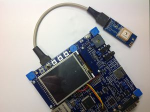
Module on MCBSTM32C Keil board
Using the STM32F107VC remapped USART1 to PB6 (USART1_TX)and PB7 (USART1_RX). The GPS module uses VCC and GND and not RS232 levels on TX/RX. Five boards are modified for the five GPS modules bought.
- The [1] show that PB6 is used for CAN2 bus TX. CAN2 bus can't be used at the same time as the GPS module.
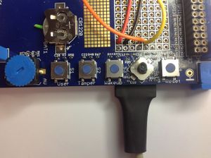
- The [2] show that PB7 is used for the USER button. To use PB7 as RX from the GPS module it is necessary to remove C20. The USER switch can't be used at the same time as the GPS module.
Connections
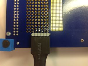
Solder a 6 pin 0,1 inch 90 degrees angle. See picture 2 and connect
- Pin 1 to 3,3V (Red wire)
- Pin 2 to GND (Black wire)
- Pin 3 - Not used in this project ( 1 second pulse signal from GPS module )
- Pin 4 to PB7 (Orange wire) - GPS module TX
- Pin 5 to PB6 (Yellow wire) - GPS module RX
- Pin 6 - NOt used in this project ( FIX signal )
Battery connector on keil board
The minus pole on the battery has no electrical connection to the main board. To make a connection a desisolated wire was placed between the minuspole on the battery and the goldplated area on the PCB under the battery. See picture 2.
USART 1 code
Communication with the GPS module has been achieved through expansion of the Keil RTX_Blinky example. This code is written using Keil uVision4.
Code for configuration and setup of USART1
int main (void)
{
        SystemInit();                             /* initialize clocks             */

        /* Setup GPIO for LEDs                                                     */
        RCC->APB2ENR |=  1 <<  6;                 /* Enable GPIOE clock            */
        GPIOE->CRH    = 0x33333333;               /* Configure the GPIO for LEDs   */

        GLCD_Init();                              /* Initialize the GLCD           */
        GLCD_Clear(White);                        /* Clear the GLCD                */

	//Enable Port B clock and configure USART1 (with remapping of USART1 to Port B from Port A)
	RCC->APB2ENR |= 1 << 3;
	RCC->CFGR  |= 4 << 10;
	RCC->APB2ENR |= 1 << 0;
	AFIO->MAPR |= 1 << 2;

	//Enable GPIOB7 as rx, GPIOB6 as tx (Pin7: 0100, Pin6: 1011)
        GPIOB->CRL &= 0x00FFFFFF;
        GPIOB->CRL |= 0x4B000000;

	//Enable USART in RCC_APB2ENR
	RCC->APB2ENR |= 1 << 14;

	/*
	Set baud rate (USART_BRR): BaudRate =   fck / ( 16 * USARTDIV )
	    For example:
	        fck = 72 MHz
		    required Baud Rate = 9600

		    USARTDIV = fck/(16 * BaudRate ) = 72000000/(16 * 9600) = 468.75

		    Mantissa = 438 - as hex: 0x1D4
		    Fraction = 16*0.75 = 12 - as hex: 0xC

		    See Reference Manual for further details
	*/
	USART1->BRR = 0x01d4c;

	//USART enable
	USART1->CR1 |= 1 << 13;

	//USART Tx enable
	USART1->CR1 |= 1 << 3;

	//USART Rx enable
	USART1->CR1 |= 1 << 2;

	//USART Rx Interrupt enable
	USART1->CR1 |= 1 << 5;

	//Send initialisation messages to the GPS, 1: Baud rate, 2: Reset GPS to output default NMEA messages
	putstr("$PMTK251,9600*17\r\n");
	putstr("$PMTK314,-1*04\r\n");

	NVIC_EnableIRQ(USART1_IRQn);

        os_sys_init (init);        /* Initialize RTX and start init */
}

void usart1_tx(char character)
{
	while ((USART1->SR & ( 1 << 6)) == 0) {}; // Wait HSERDY = 1
	USART1->DR = (uint16_t) character;
}

void putstr(char *string)
{
	int i;
	for ( i=0; string[i] != 0; i++ )
        {
		usart1_tx(string[i]);
	}
}

//USART1 Interrupt Handler

void USART1_IRQHandler(void) __irq
{
	NVIC_DisableIRQ(USART1_IRQn);

	//Send event flag to t_gps task
	isr_evt_set(0x1111, t_gps);

	//Reset USART status register to allow the next value from the serial link to be set
	USART1->SR &= ~(1 << 5);

	NVIC_EnableIRQ(USART1_IRQn);
}
Code for handling incoming data
// Global array received[] used to allow output to be seen in debugger.
// Use of the global array would also be relevant to allow data to be passed between tasks.
// This approach would require use of mutexes when writing to and reading from the array, to ensure that only complete messages are saved
// This is a very minimal implementation to allow viewing of received messages in the debugger.
// More work is required to make a robust character buffer...

__task void gps(void)
{
	int i = 0;
        for(;;)
	{
	     os_evt_wait_and(0x1111, 0xffff);
	     received[i] = USART1->DR;

             // Check for standard NMEA message ending (CR/LF)
             if(received[i]==0x0A  && received[i-1]==0x0D)
	     {
                i=0;
	     }
	     else
	     {
	         i++;
	         i=i%MAX_MESSAGE_SIZE;
	     }
	}
}
General configuration and setup
OS_TID t_phaseA;                        /* assigned task id of task: phase_a */
OS_TID t_phaseB;                        /* assigned task id of task: phase_b */
OS_TID t_phaseC;                        /* assigned task id of task: phase_c */
OS_TID t_phaseD;                        /* assigned task id of task: phase_d */
OS_TID t_clock;                         /* assigned task id of task: clock   */
OS_TID t_lcd;                           /* assigned task id of task: lcd     */
OS_TID t_gps;			        /* assigned task id of task: gps     */

OS_MUT mut_GLCD;                        /* Mutex to control GLCD access     */

#define LED_A   0
#define LED_B   1
#define LED_C   2
#define LED_D   3
#define LED_CLK 7

#define LED_NUM     8                   /* Number of user LEDs                */

#define MAX_MESSAGE_SIZE 100
const long led_mask[] = { 1<<15, 1<<14, 1<<13, 1<<12, 1<<11, 1<<10, 1<<9, 1<<8 };
unsigned char received[MAX_MESSAGE_SIZE];
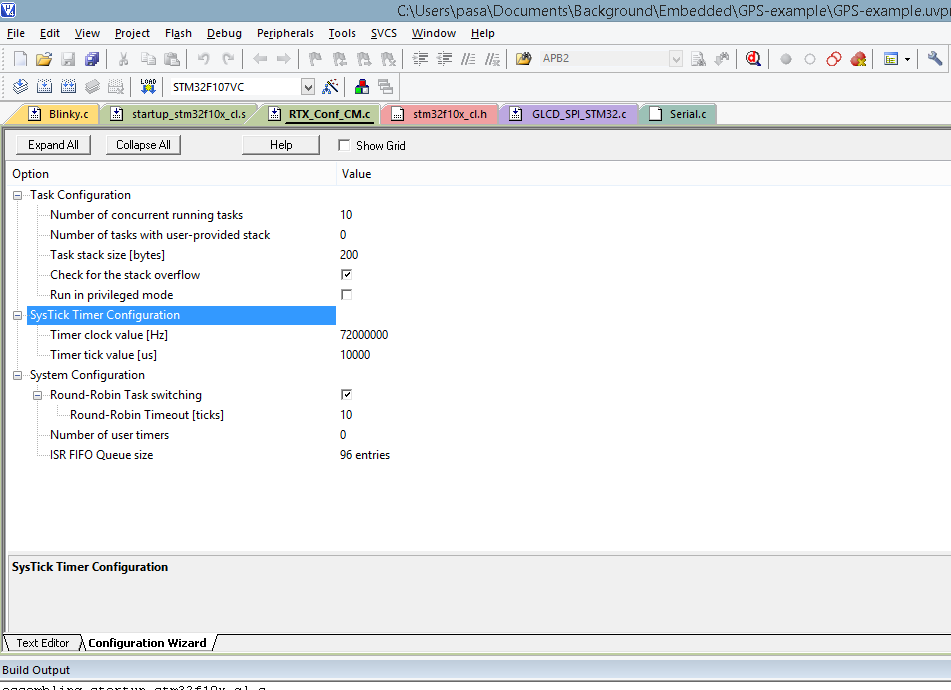
Configuration settings for RTX
Data sheets
- Digilent PB200 datasheet
- Binary Protocol
- MTK Commands
- MTK Commands
- Mediatek 3329.pdf
- USARTS on MCBSTM32C
ARM board projects


