Difference between revisions of "Enterprise Data Center Design"
m (→6500 Services Module Placement Considerations) |
m (→Designing the Access Layer) |
||
| Line 100: | Line 100: | ||
Route Health Injection(RHI) tillader at en Cisco CSM/ACE i en 6500 switch installerer en hoste route til den virtuelle server. /32 routen fjerner problemer med asymmetriske routing. | Route Health Injection(RHI) tillader at en Cisco CSM/ACE i en 6500 switch installerer en hoste route til den virtuelle server. /32 routen fjerner problemer med asymmetriske routing. | ||
=Designing the Access Layer= | =Designing the Access Layer= | ||
| + | {| | ||
| + | |[[Image:ScreenShot404.jpg|800px|left|thumb|VRFs in the datacenter]] | ||
| + | |} | ||
| + | ==Layer 2 looped== | ||
| + | VLANs are extended into the aggregation layer. Layer 2 services | ||
| + | such as NIC teaming, clustering, and stateful services from the aggregation layer such | ||
| + | as a firewall, SLB, and SSL can be provided across Layer 2 models. Layer 3 routing is | ||
| + | first performed in the aggregation layer. | ||
| + | {| | ||
| + | |[[Image:ScreenShot405.jpg|800px|left|thumb|Layer 2 Looped designs]] | ||
| + | |} | ||
| + | The Layer 2 looped triangle in Figure 5-14 has the following features: | ||
| + | *Supports VLAN extension/Layer 2 adjacency across the access layer. | ||
| + | *Resiliency is achieved with dual-homing and RSTP. | ||
| + | *Quick convergence with RSTP. | ||
| + | *Supports stateful services at the aggregation layer. | ||
| + | *Proven and widely used. | ||
| + | The Layer 2 looped square in Figure 5-14 has the following features: | ||
| + | *Supports VLAN extension/Layer 2 adjacency across the access layer. | ||
| + | *Resiliency is achieved with dual homing and STP. | ||
| + | *Quick convergence with 802.1w and 802.1s. | ||
| + | *Supports stateful services at the aggregation layer. | ||
| + | *Supports more access layer switches, optimizing 10 Gigabit Ethernet aggregation layer density. | ||
| + | *Active/active uplinks align well to active/active service module designs. | ||
| + | ==Layer 2 loop free== | ||
| + | VLANs are not extended into the aggregation layer. Layer 2 services are supported. Layer 3 routing is first performed in the aggregation layer. | ||
| + | {| | ||
| + | |[[Image:ScreenShot406.jpg|800px|left|thumb|Loop-Free]] | ||
| + | |} | ||
| + | The following are characteristics of loop-free U access: | ||
| + | *VLANs are contained in switch pairs (no extension outside of switch pairs). | ||
| + | *No STP blocking; all uplinks are active. | ||
| + | *Layer 2 service modules black-hole traffic on uplink failure. | ||
| + | The following are characteristics of loop-free inverted U access: | ||
| + | *Supports VLAN extension. | ||
| + | *No STP blocking; all uplinks are active. | ||
| + | *Access switch uplink failure black-holes single attached servers. | ||
| + | *ISL scaling considerations. | ||
| + | *Supports all service module implementations. | ||
| + | ==Layer 3== | ||
| + | Stateful services requiring Layer 2 connectivity cannot be provisioned from | ||
| + | the aggregation layer. Layer 3 routing is first performed in the access layer. | ||
= Eksterne henvisninger = | = Eksterne henvisninger = | ||
Revision as of 15:45, 7 September 2010
Kapitel 5 fra CCDP ARCH bogen.
Contents
Cisco Catalyst 6500 serie switches Cisco Data Center Technologies
Designing The Core and Aggregation Layers
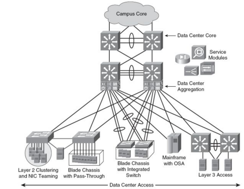
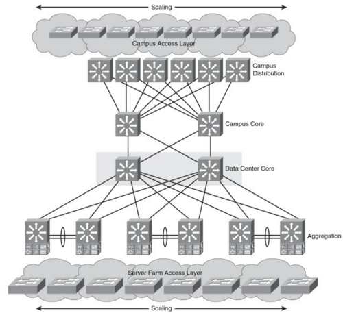
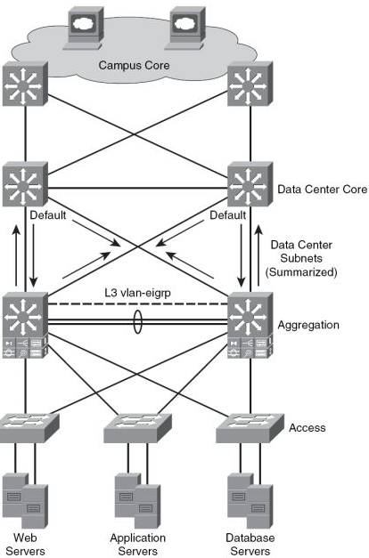
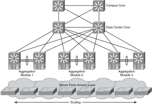
Data Center arkitekturen er baseret på en tre lags model.
- Core laget består af høj-hastigheds OSI lag 3.
- Aggregation laget forbinder Access-Laget med enten OSI lag 2 eller OSI lag 3.
- Access Laget giver fysisk forbindelse til Serverne.
fordele ved tre-lags modellen
- Hvis det er nødvendigt at samme VLAN skal være på flere Access Switche samtidig kan Aggregation-Switchene-----
Data Center Core layer design
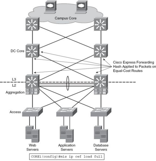
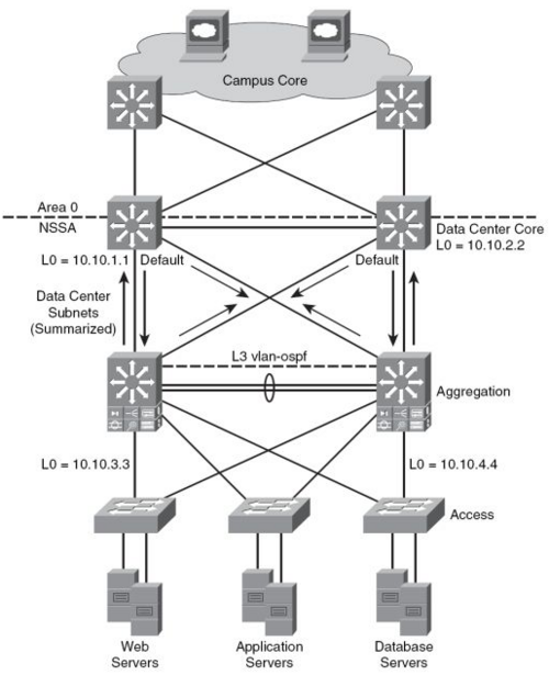
Routnings Protokoller
OSPF
EIGRP
Aggregation Layer
Spanning tree design
Cisco anbefaler at benytte sig af RPVST+.
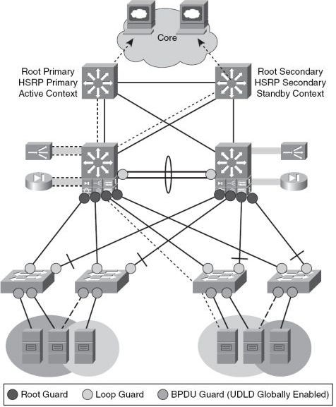
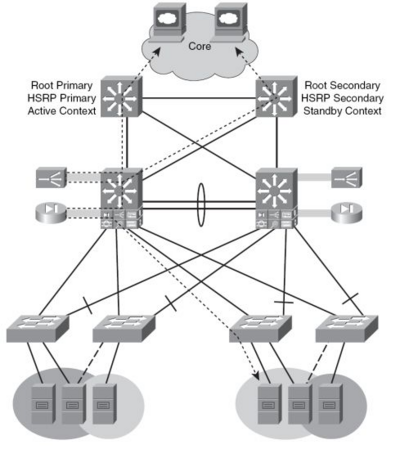
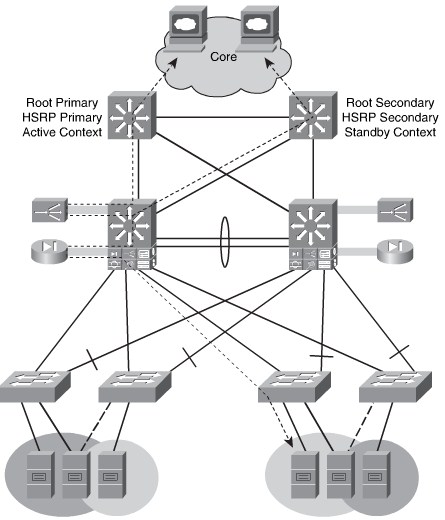
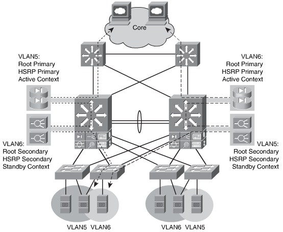
Aktiv STP,HSRP og Service Context Alignment
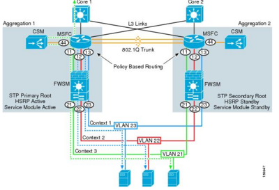
Active/Standby Service Module Design
I tegningen herunder er den ene Aggregation Switch Active og den anden Standby for al trafikken fra Access laget.
- Cisco 6500 med FSWM 2.x
Active/Active Service Module Design
I tegningen herunder er begge Aggregation Switche Active for hver deres VLAN's.
- Cisco 6500 med FSWM 3.1
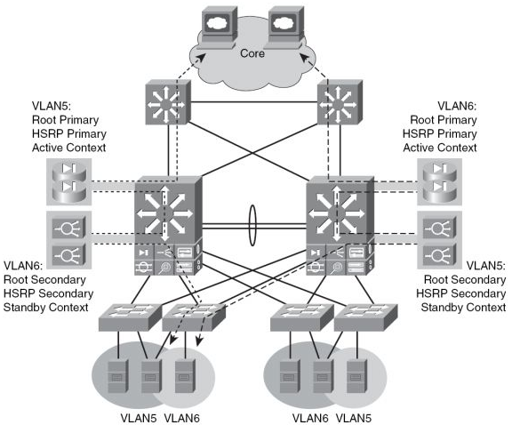
|
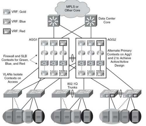
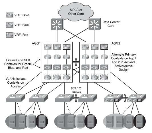
Anvendelse af VRF (MPLS) i Data centeret
Access Lag
Lag 2 - Looped design
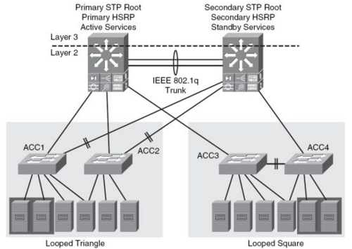
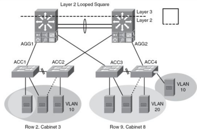
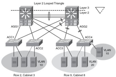
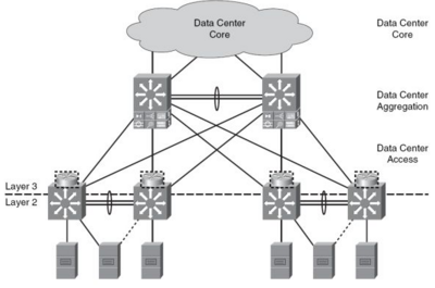
I Lag to Looped Design er VLAN's termineret i Aggregation laget og Lag 2 services som NIC teaming, Clustering og Statefull Services som for eksempel Firewall, Server Load Balancing, SSL kan udføres på ISO lag 2. Lag tre Routning foregår på Aggregations laget.
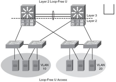
Lag 2 - Loop frit design
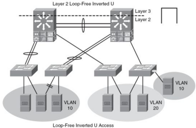
I Lag to Loop frit design er der ikke VLAN på Aggregationslaget modsat Looped design (Se overnfor). Ved omvendt U er det dog muligt at have VLAN på Aggregationslaget. Lag to services er supporteret. Lag tre Routning foregår på Aggregations laget.
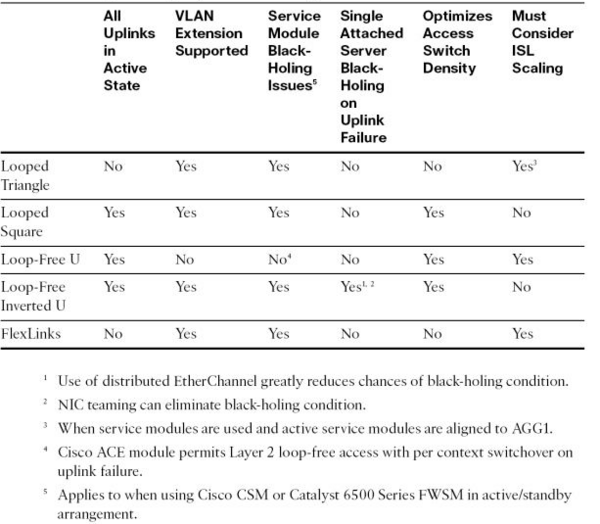
Sammenligning af lag to Access designs
Lag 3 på Access laget
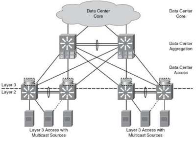
Statefull Services som kræver lag to konnektivitet kan ikke udføres af Aggregationslaget hvis Lag tre Routning foregår på Access-laget.
Multicast Source Support
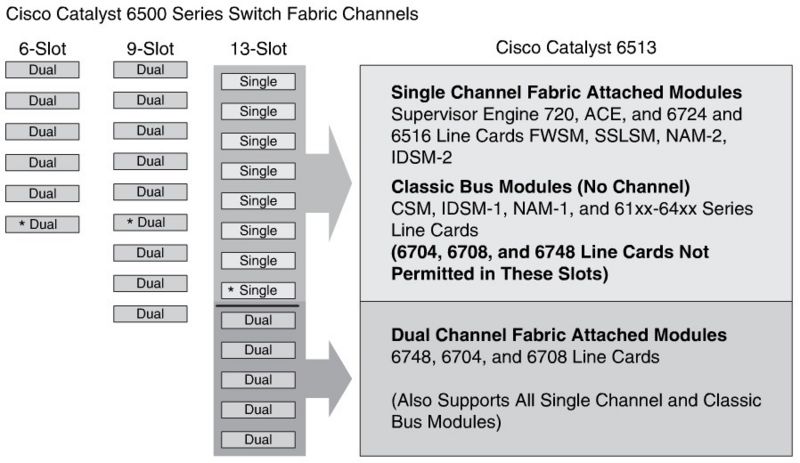
6500 Services Module Placement Considerations
Active STP, HSRP, and Service Context Alignment
Establisheing Inbound Path Prefenrece
Route Health Injection(RHI) tillader at en Cisco CSM/ACE i en 6500 switch installerer en hoste route til den virtuelle server. /32 routen fjerner problemer med asymmetriske routing.
Designing the Access Layer
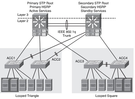
Layer 2 looped
VLANs are extended into the aggregation layer. Layer 2 services such as NIC teaming, clustering, and stateful services from the aggregation layer such as a firewall, SLB, and SSL can be provided across Layer 2 models. Layer 3 routing is first performed in the aggregation layer.
The Layer 2 looped triangle in Figure 5-14 has the following features:
- Supports VLAN extension/Layer 2 adjacency across the access layer.
- Resiliency is achieved with dual-homing and RSTP.
- Quick convergence with RSTP.
- Supports stateful services at the aggregation layer.
- Proven and widely used.
The Layer 2 looped square in Figure 5-14 has the following features:
- Supports VLAN extension/Layer 2 adjacency across the access layer.
- Resiliency is achieved with dual homing and STP.
- Quick convergence with 802.1w and 802.1s.
- Supports stateful services at the aggregation layer.
- Supports more access layer switches, optimizing 10 Gigabit Ethernet aggregation layer density.
- Active/active uplinks align well to active/active service module designs.
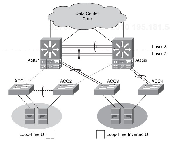
Layer 2 loop free
VLANs are not extended into the aggregation layer. Layer 2 services are supported. Layer 3 routing is first performed in the aggregation layer.
The following are characteristics of loop-free U access:
- VLANs are contained in switch pairs (no extension outside of switch pairs).
- No STP blocking; all uplinks are active.
- Layer 2 service modules black-hole traffic on uplink failure.
The following are characteristics of loop-free inverted U access:
- Supports VLAN extension.
- No STP blocking; all uplinks are active.
- Access switch uplink failure black-holes single attached servers.
- ISL scaling considerations.
- Supports all service module implementations.
Layer 3
Stateful services requiring Layer 2 connectivity cannot be provisioned from the aggregation layer. Layer 3 routing is first performed in the access layer.
 This article is under development....