Difference between revisions of "CCNP SWITCH/Implementing VLANs in Campus Networks"
m (→VTP Version 3) |
m (→LACP Modes) |
||
| Line 347: | Line 347: | ||
;Passiv | ;Passiv | ||
:Places a port in a passive negotiating state. In this state, the port responds to the LACP packets that it receives but does not initiate LACP packet negotiation (default). | :Places a port in a passive negotiating state. In this state, the port responds to the LACP packets that it receives but does not initiate LACP packet negotiation (default). | ||
| − | ; | + | ;Active |
:Places a port in an active negotiating state. In this state, the port initiates negotiations with other ports by sending LACP packets. | :Places a port in an active negotiating state. In this state, the port initiates negotiations with other ports by sending LACP packets. | ||
;On | ;On | ||
| Line 354: | Line 354: | ||
|[[Image:ScreenShot1090.jpg|800px|left|thumb|LACP]] | |[[Image:ScreenShot1090.jpg|800px|left|thumb|LACP]] | ||
|} | |} | ||
| + | |||
==Layer 2 EtherChannel Configuration== | ==Layer 2 EtherChannel Configuration== | ||
{| | {| | ||
Revision as of 09:13, 23 August 2011
Contents
- 1 VLANs
- 2 Implementing Trunking in Cisco Campus Network
- 3 VLAN Trunking Protocol
- 4 Private VLANs
- 5 Configuring Link Aggregation with EtherChannel
- 6 Summary
VLANs
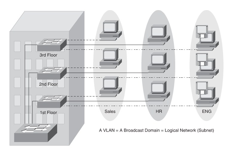
VLAN definition
Trunking:
- ISL(Is not a part of this exam)
- 802.1Q(The Industry standard)
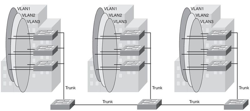
End-To-End VLANs
- Each VLAN is dispersed geographically throughout the network.
- Users are grouped into each VLAN regardless of the physical location.
- As a user moves throughout a campus, the VLAN membership of that user remains
the same, regardless of the physical switch to which this user attaches.
- Users are typically associated with a given VLAN for network management reasons.
This is why they are kept in the same VLAN, therefore the same group, as they move through the campus.
- All devices on a given VLAN typically have addresses on the same IP subnet
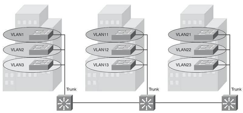
Local VLANs
- The network administrator should create local VLANs with physical boundaries in
mind rather than the job functions of the users on the end devices.
- Generally, local VLANs exist between the access and distribution levels.
- Traffic from a local VLAN is routed at the distribution and core levels to reach desti-
nations on other networks.
- Configure the VTP mode in transparent mode because VLANs on a given access
switch should not be advertised to all other switches in the network, nor do they need to be manually created in any other switch’s VLAN database.
- A network that consists entirely of local VLANs can benefit from increased conver-
gence times offered via routing protocols, instead of a spanning tree for Layer 2 net- works. It is usually recommended to have one to three VLANs per access layer switches.
Comparison of End-to-End VLANs and Local VLANs
Reasons for using End-To-End VLANs
- Grouping users:Users can be grouped on a common IP segment, even though they are geographically dispersed. Recently the trend has been moving toward virtualization. Solutions such as VMWARE need end-to-end VLANs to be spread across segments of the campus.
- Applying quality of service (QoS):Traffic can be a higher or lower access priority to network resources from a given VLAN.
- Routing avoidance:If much of the VLAN user traffic is destined for devices on that same VLAN, and routing to those devices is not desirable, users can access resources on their VLAN without their traffic being routed off the VLAN, even though the traffic might traverse multiple switches.
- Special purpose VLAN:Sometimes a VLAN is provisioned to carry a single type of traffic that must be dispersed throughout the campus (for example, multicast, voice, or visitor VLANs).
- Poor design:For no clear purpose, users are placed in VLANs that span the campus or even span WANs. Sometimes when a network is already configured and running, organizations are hesitant to improvethe design because of downtime or other political reasons.
- Finally, troubleshooting devices on a campus with end-to-end VLANs can be challenging because the traffic for a single VLAN can traverse multiple switches in a large area of the campus, and that can easily cause potential spanning-tree problems.
Mapping VLANs to a Hierarchical Network
In the past, network designers have attempted to implement the 80/20 rule when design-
ing networks. Today it is reversed to 20/80 because most traffic will end in the Data Center.
End-To-End VLANs was attractive when IP addresses were manually administered. Today most networks use DHCP.
In addition, because STP is configured for redun-
dancy, the switch limits the STP to only the access and distribution switches that help to
reduce the network complexity in times of failure.
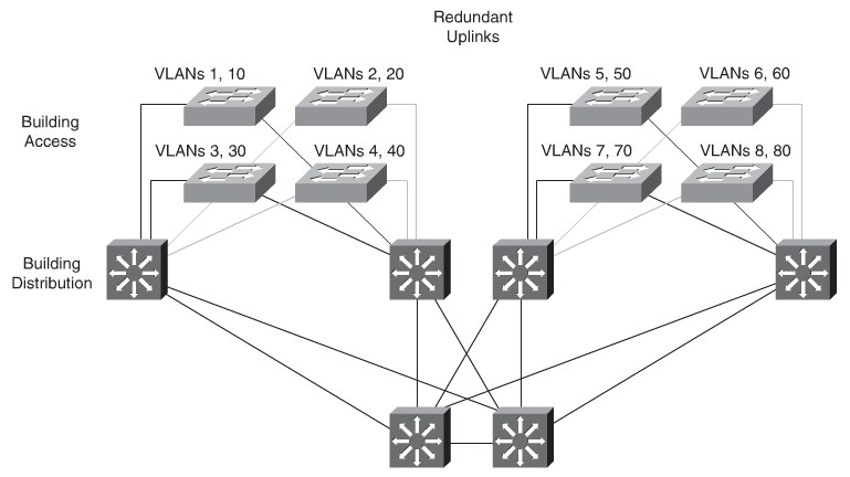
Implementing the enterprise campus architecture design using local VLANs provides the
following benefits:
- Deterministic traffic flow:The simple layout provides a predictable Layer 2 and Layer 3 traffic path.
- Active redundant paths:When implementing Per VLAN Spanning Tree (PVST) or Multiple Spanning Tree Protocol (MSTP) because there is no loop, all links can be used to make use of the redundant paths.
- Finite failure domain:If VLANs are local to a switch block, and the number of devices on each VLAN is kept small, failures at Layer 2 are confined to a small subset of users.
- Scalable design:Following the enterprise campus architecture design, new access switches can be easily incorporated, and new submodules can be added when necessary.
Best Practices for VLAN Design
- For the Local VLANs model, it is usually recommended to have only one to three VLANs per access module
- Avoid using VLAN 1 as the “blackhole” for all unused ports.
- Try to always have separate voice VLANs, data VLANs, management VLANs, native VLANs, blackhole VLANs, and default VLANs (VLAN 1).
- In the local VLANs model, avoid VTP.
- For trunk ports, turn off DTP and configure it manually. Use IEEE 802.1Q rather than ISL
- Manually configure access ports.
- Prevent all data traffic from VLAN 1; only permit control protocols to run on VLAN1 (DTP, VTP, STP BPDUs, PAgP, LACP, CDP, and such.)
- Avoid using Telnet because of security risks; enable SSH support on management VLANs.
Configuring VLANs
Cisco Catalyst switches support up to 4096 VLANs depending on the platform and software version.
See Cisco Catalyst Switch Guide
| VLAN Range | Range | Usage | Propagated via VTP |
|---|---|---|---|
| 0, 4095 | Reserved | For system use only. You cannot see or use these VLANs. | - |
| 1 | Normal | Cisco default. You can use this VLAN, but you cannot delete | Yes |
| 2-1001 | Normal | For Ethernet VLANs. You can create, use, and delete these VLANs. | Yes |
| 1002–1005 | Normal | Cisco defaults for FDDI and Token Ring. You cannot delete VLANs 1002–1005. | Yes |
| 1006–1024 | Reserved | For system use only. You cannot see or use these VLANS. | - |
| 1025–4094 | Extended | For Ethernet VLANs only. | Not supported in VTP versions 1 and 2. The switch must be in VTP transparent mode to configure extended- range VLANS. Only supported in version 3. |
Switch#<input>show vlan brief</input>

VLAN Name                             Status    Ports
---- -------------------------------- --------- -------------------------------
1    default                          active    Fa0/1
100  VLAN0100                         active    Fa0/2, Fa0/3, Fa0/4, Fa0/5, Fa0/6, Fa0/7, Fa0/8, Fa0/9, Fa0/10
                                                Fa0/11, Fa0/12, Fa0/13, Fa0/14, Fa0/15, Fa0/16, Fa0/17, Fa0/18
                                                Fa0/19, Fa0/20, Fa0/21, Fa0/22, Fa0/23, Fa0/24
200  VLAN0200                         active
300  VLAN0300                         active
1002 fddi-default                     act/unsup
1003 trcrf-default                    act/unsup
1004 fddinet-default                  act/unsup
1005 trbrf-default                    act/unsup
Configure VLANs
Switch# <input>configure terminal</input>
Switch(config)# <input>vlan 5</input>
Switch(config-vlan)# <input>name Engineering</input>
Switch(config-vlan)# <input>exit</input>
Switch(config)#<input> no vlan 5</input>
Switch(config)# <input>end</input>
Assign an Access Port to a VLAN
Switch# <input>configure terminal</input>
Enter configuration commands, one per line. End with CNTL/Z.
Switch(config)# <input>interface FastEthernet 0/1</input>
Switch(config-if)# <input>description PC A</input>
Switch(config-if)# <input>switchport</input>
Switch(config-if)# <input>switchport host</input>
Switch(config-if)# <input>switchport mode access</input>
Switch(config-if)# <input>switchport access vlan 200</input>
Switch(config-if)# <input>no shutdown</input>
Switch(config-if)# <input>end</input>
The switchport host command effectively configures a port for a host device, such as a workstation or server. This feature is a macro for enabling SpanningTree PortFast and dis abling EtherChanneling on a per-port basis. These features are discussed in later chapters. The switchport mode access command is needed so that the interface doesn’t attempt to negotiate trunking.
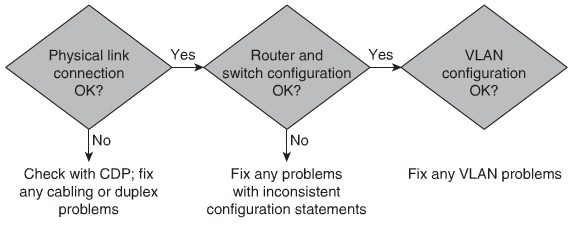
Troubleshooting VLANs
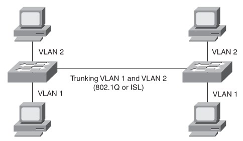
Implementing Trunking in Cisco Campus Network
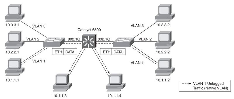
Allows different VLANs to traverse a singe link. 802.1Q Needs a matching nativ VLAN on all trunks.
Trunking Protocols
- ISL: A Cisco proprietary trunking encapsulation(not used anymore)
- IEEE 802.1Q:An industry-standard trunking method
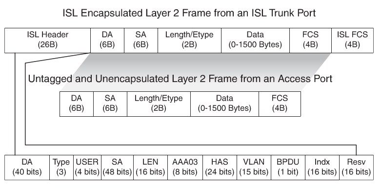
ISL Frames
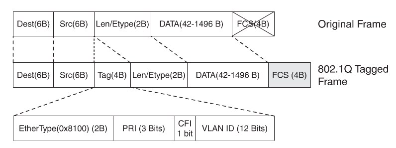
IEEE802.1Q
The IEEE 802.1Q/802.1p standard provides thefollowing inherent architectural advan- tages over ISL:
- Smaller frame overhead than ISL.
- 802.1Q is a widely supported industry-standard protocol.
- 802.1Q has the support for 802.1p fields for QoS.
802.1Q tag fields:
- EtherType(TPID):Set to 0x8100 to specify that the 802.1Q tag follows.
- PRI:3-bit 802.1p priority field
- CFI:Canonical Format Identifier; is always set to 0 for Ethernet switches and to 1 for Token Ring-type networks.
- VLAN ID:12-bit VLAN field. Of the 4096 possible VLAN IDs, the maximum number of possible VLAN configurations is 4094. A VLAN ID of 0 indicates priority frames, and value 4095 (FFF) is reserved. CFI, PRI, and VLAN ID are represented as Tag Control information (TCI) fields.
IEEE802.1Q recalculates the CRC value for the entire frame with the tag, and inserts the new CRC value in a new FCS. ISL,in comparison, wraps the original frame and adds a second FCS to the frame.
Nativ VLANs
Be aware of native VLAN mismatch could cause STP Loops. CDP issues a Native VLAN Mismatch error.
Dynamic Trunking Protocol (DTP)
Cisco proprietary point-to-point protocol that negotiates the operational mode of directly connected switch ports to a trunk port and selects an appropriate trunking protocol.
- Access
- Puts the interface into permanent nontrunking mode and negotiates to convert the link into a nontrunk link.
- Trunk
- Puts the interface into permanent trunking mode and negotiates to convert the link into a trunk link.
- Nonegotioate
- Puts the interface into permanent trunking mode but prevents the interface from generating DTP frames.
- Dynamic desirable
- Makes the interface actively attempt to convert the link to a trunk link.
- Dynamic auto
- Makes the interface willing to convert the link to a trunk link.
Configure 802.1Q Trunking
Switch# <input>configure terminal</input>
Enter configuration commands, one per line. End with CNTL/Z.
Switch(config)# <input>interface FastEthernet 0/1</input>
Switch(config-if)# <input>switchport trunk encapsulation dot1q</input>
Switch(config-if)# <input>switchport mode dynamic desirable</input>
Switch(config-if)# <input>no shutdown</input>
Switch(config-if)# <input>end</input>
Verify 802.1Q Trunking
Switch# <input>show interfaces FastEthernet 5/8 switchport</input>
Name: Fa5/8
Switchport: Enabled
Administrative Mode: dynamic desirable
Operational Mode: trunk
Administrative Trunking Encapsulation: negotiate
Operational Trunking Encapsulation: dot1q
Negotiation of Trunking: Enabled
Access Mode VLAN: 1 (default)
Trunking Native Mode VLAN: 1 (default)
Trunking VLANs Enabled: ALL
Pruning VLANs Enabled: 2-1001
VLAN Trunking Protocol
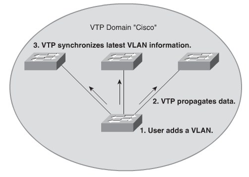
VTP minimizes misconfigurations and configuration inconsistencies that might result in various problems. Switches transmit VTP messages only on 802.1Q or ISL trunks. Cisco switches transmit VTP summary advertisements over the management VLAN (VLAN 1 by default) using a Layer 2 multicast frame with a destination MAC address of 01-00-0C-CC-CC-CC
VTP Versions include 1,2 and 3. VTP Version 3 is not a scope of this book.
VTP Modes
- Client
- Cannot create, change, or delete VLANs on command-line interface (CLI).
Forwards advertisements to other switches.
Synchronizes VLAN configuration with latest information received from other switches in the management domain.
Does not save VLAN configuration in nonvolatile RAM (NVRAM). - Server
- Creates, modifies, and deletes VLANs.
Sends and forwards advertisements to other switches.
Synchronizes VLAN configuration with latest information received from other switches in the management domain.
Saves VLAN configuration in NVRAM. - Transparent
- Creates, deletes, and modifies VLANs only on the local switch.
Forwards VTP advertisements received from other switches in the same management domain.
Does not synchronize its VLAN configuration with information received from other switches in the management domain.
Saves VLAN configuration in NVRAM.
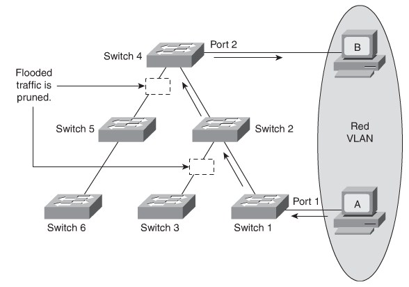
VTP Pruning
VTP Versions
VTP version 2 features that are not implemented in VTP version 1:
- Token Ring support:VTP version 2 supports Token Ring LAN switching and Token Ring VLANs.
- Unrecognized Type-Length-Value (TLV) support:A VTP version 2 server or client propagatesconfiguration changes to its other trunks even for TLVs that it cannot parse.
- Version-independent transparent mode:In VTP version 1, a VTP-transparent switch inspects VTP messages for the domain name and version and forwards a message only if the version and domain name match.
- Consistency checks:VTP version 2 performs VLAN consistency checks(such as VLAN names and values) only when you enter new information through the CLI or via the Simple Network Management Protocol(SNMP).
VTP Version 3
- Support for extended VLANs (1025 to 4094)
- Support for the creation and advertising of Private VLANs
- Interaction with VTP versions 1 and 2
- Configurable on a per-port basis
VTP Message Types
- Summary Advertisements: Send every 5 minutes or when revision number changes. Summary advertisements includes domain and revision number.
- Subset Advertisements: Subset advertisement follow a summary advertisement to inform clients about changes.
- Advertisement Requests: A switch sends a Requeste advertisement when the switch have been reset. The VTP domain name has changed or it gets a summary with higher revision number than its own.
Configure VTP
Switch# <input>configure terminal</input>
Switch(config)# <input>vtp mode server</input>
Setting device to VTP SERVER mode.
Switch(config)# <input>vtp domain Lab_Network</input>
Switch(config)# <input>end</input>
Private VLANs
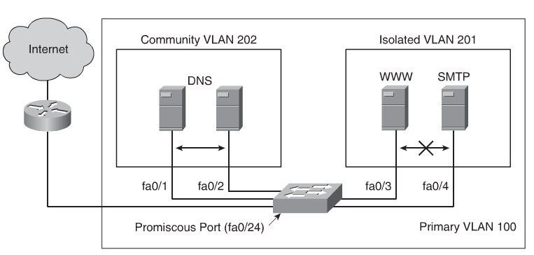
Port Types
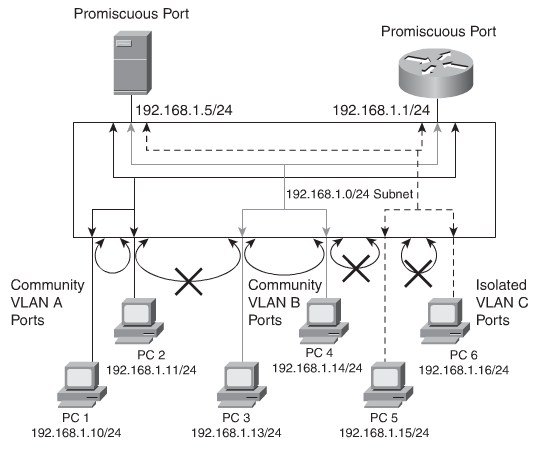
- Isolated:An isolated port has complete Layer 2 separation from other ports within the same Private VLAN, exceptfor the promiscuous ports
- Promiscuous:A promiscuous port can communicate with all ports within the Private VLAN, including the community and isolated ports.
- Community:Communityports communicate among themselves and with their promiscuous ports.
Private VLAN Types
- A primary Private VLAN:The high-level VLAN of the Private VLAN.
- A secondary Private VLAN:Every secondary Private VLAN is a child to a primary Private VLAN and is mapped to one primary Private VLAN
- Community Private VLANs:Ports that belong to the community Private VLAN cancommunicate with the other ports in the same community.
- Isolated Private VLANs:Ports that belong to an isolated Private VLAN can communicate only with promiscuous ports.
Configure Private VLANs
- Set the vtp mode to transparent
- Switch(config)#vtp mode transparent
- Create Primary PVLAN
- Switch(config)#vlan pvlan-id
- Switch(config)#private-vlan primary
- Switch(config)#name primary-vlan
- Switch(config)#exit
- Create the isolated VLAN
- Switch(config)#vlan secondary-vlan-id
- Switch(config)#private-vlan isolated
- Switch(config)#name isolated-pv-lan
- Switch(config)#exit
- Bind the isolated VLAN to the primary VLAN
- Switch(config)#vlan primary-vlan-id
- Switch(config)#private-vlan assosiation secondary-vlan-id
- Switch(config)#exit
- Configure Host ports
- Switch(config)#interface FastEthernet0/1
- Switch(config-if)#switchport private-vlan host primary_vlan_id secondary_vlan_id
- Switch(config-if)#switchport mode private-vlan host
- Switch(config-if)#exit
- Configure the promiscuous port
- Switch(config)#interface FastEthernet0/1
- Switch(config-if)#switchport private-vlan mapping primary_vlan_id secondary_vlan_id
- Switch(config-if)#switchport mode private-vlan promiscuous
- Switch(config-if)#exit
sw(config)# <input>vtp transparent</input>
sw(config)# <input>vlan 201</input>
sw(config-vlan)# <input>private-vlan isolated</input>
sw(config)#<input> vlan 202</input>
sw(config-vlan)# <input>private-vlan community</input>
sw(config-vlan)# <input>vlan 100</input>
sw(config-vlan)# <input>private-vlan primary</input>
sw(config-vlan)#<input> private-vlan association 201,202</input>
sw(config-vllan)# <input>interface fastethernet 0/24</input>
sw(config-if)# <input>switchport mode private-vlan promiscuous</input>
sw(config-if)# <input>switchport private-vlan mapping 100 201,202</input>
sw(config-if)#<input> interface range fastethernet 0/1 - 2</input>
sw(config-if)# <input>switchport mode private-vlan host</input>
sw2(config-if)# <input>switchport private-vlan host-association 100 202</input>
sw(config-if)#<input> interface range fastethernet 0/3 - 4</input>
sw(config-if)# <input>switchport mode private-vlan host</input>
sw2(config-if)# <input>switchport private-vlan host-association 100 201</input>
Configuring Link Aggregation with EtherChannel
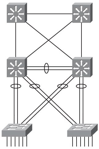
EtherChannel is a technology that was originally developed by Cisco as a LAN switch-to-switch technique of grouping several Fast or Gigabit Ethernet ports into one logical channel.
Etherchannel includes these benefits:
- It relies on the existing switch ports: There is no need to upgrade the switch-to-switch link to a faster and more expensive connection.
- Most of the configuration tasks can be done on the EtherChannel interface instead of each individual port
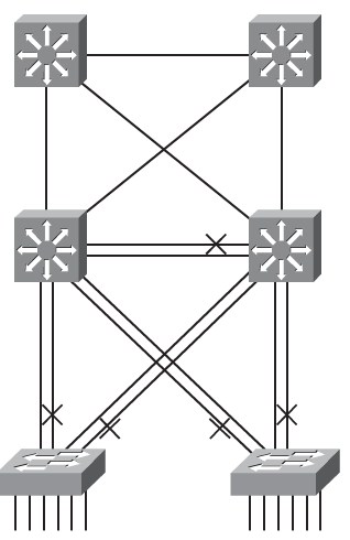
- EtherChannel provides redundancy: As the overall link is seen as one logical connection, the loss of one physical link does not create a change in the topology.
- Load balancing is possible between the links part of the same EtherChannel.
PAgP and LACP Protocols
- The Port Aggregation Protocol (PAgP) is a Cisco Proprietary protocol
- LACP is part of an IEEE specification (802.3ad)
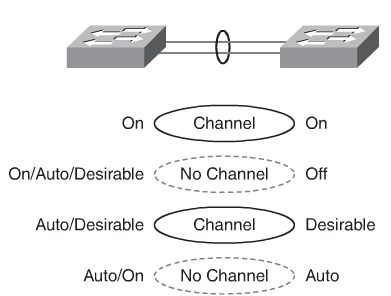
PAgP modes
PAgP packets are sent every 30 seconds.
- Auto
- Places an interface in a passive negotiating state in which the interface responds to the PAgP packets that it receives but does not initiate PAgP negotiation (default).
- Desirable
- Places an interface in an active negotiating state in which the interface initiates negotiations with other interfaces by sending PAgP packets.
- On
- Forces the interface to channel without PAgP. Interfaces configured in the “on” mode do not exchange PAgP packets.
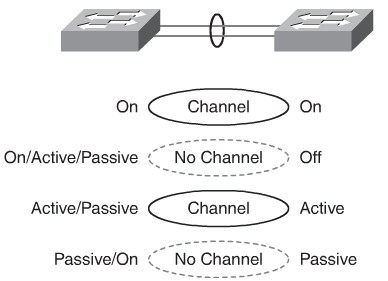
LACP Modes
LACP provides the same negotiation benefits as PAgP.
- Passiv
- Places a port in a passive negotiating state. In this state, the port responds to the LACP packets that it receives but does not initiate LACP packet negotiation (default).
- Active
- Places a port in an active negotiating state. In this state, the port initiates negotiations with other ports by sending LACP packets.
- On
- Forces the interface to the channel without PAgP or LACP.
Layer 2 EtherChannel Configuration
Switch(config)#<input> interface fastethernet 0/23</input>
Switch(config-if)# <input>channel-group 2 mode active</input>
Switch(config)#<input> interface fastethernet 0/24</input>
Switch(config-if)# <input>channel-group 2 mode active</input>
Switch(config)# <input>interface port-channel 2</input>
Switch(config-if)# <input>switchport mode trunk</input>
Switch(config-if)#<input> switchport trunk native VLAN 99</input>
Switch(config-if)# <input>switchport trunk allowed VLAN 2,3,99</input>
!!!Remote Switch configuration
RSwitch(config)# <input>interface fastethernet 0/23</input>
RSwitch(config-if)# <input>channel-group 5 mode on</input>
RSwitch(config)# <input>interface fastethernet 0/24</input>
RSwitch(config-if)# <input>channel-group 5 mode on</input>
RSwitch(config)#<input> interface port-channel 5</input>
RSwitch(config-if)# <input>switchport mode trunk</input>
RSwitch(config-if)#<input> switchport trunk native VLAN 99</input>
RSwitch(config-if)# <input>switchport trunk allowed VLAN 2,3,99</input>
Verify EtherChannle
Switch# <input>show etherchannel summary</input>
Flags:  D - down        P - bundled in port-channel
I - stand-alone s - suspended
H - Hot-standby (LACP only)
R - Layer3      S - Layer2
U - in use      f - failed to allocate aggregator
M - not in use, minimum links not met
u - unsuitable for bundling
w - waiting to be aggregated
d - default port
Number of channel-groups in use: 2
Number of aggregators:           2
Group  Port-channel  Protocol    Ports
------+-------------+-----------+--------------------------------------------
2      Po2(SU)         LACP      g0/49(P) g0/50(P) g0/51(P) g0/52(P)
7      Po7(SU)         LACP      g0/47(P) g0/48(P)
9      Po9(SU)         PAgP      g0/8(P) g0/9(P)
EtherChannel Load Balancing Options
Load balancing options is dependent on the hardware platform.
- src-mac:Source MAC addresses
- dst-mac:Destination MAC addresses
- src-dst-mac:Source and destination MAC addresses
- src-ip:Source IP addresses
- dst-ip:Destination IP addresses
- src-dst-ip:Source and destination IP addresses (default)
- src-port:Source TCP/User Datagram Protocol (UDP) port
- dst-port:Destination TCP/UDP port
- src-dst-port:Source and destination TCP/UDP port
switch(config)#<input>port-channel load-balance src-dst-ip</input>
switch(config)#<input>end</input>
switch#<input>show etherchannel load-balance</input>
EtherChannel Load-Balancing Configuration:
src-dst-ip