Spanning tree
The Spanning Tree protocol are used on Ethernet Switches to avoid broadcast storms.
Spanning Tree has evolved during the years. See Spanning Tree articles
Contents
Problems with Switches without Spanning Tree
Broadcast Storms
A broadcast starts when a Ethernet switch receives a broadcast from a Host and there exist a loop. See example below:
Duplicate Ethernet Frames
Another problem with Ethernet loops is duplicate Ethernet frames. In the picture below, switch X can see PC-B mac-address on two ports and send the frame out of each port.
Instability in Switch MAC-Address table
Another problem with with Ethernet loops is instability in the Switches MAC-Address table See the picture below and consider:
- The MAC-Address off PC-B is timed out on both Switches.
- PC-A send a unicast packet to PC-B's MAC-Address.
- PC-B's MAC-address is unknown to Switch X which send the Frame out of all ports. (Except the originating port 3)
- Switch Y receives the Frame to PC-B on port 1 and on port 2.
- PC-B's MAC-address is unknown to Switch X which send the Frame out of all ports. (Except originating port)
- Switch X know receives Frames on port 1 and port 2 with source MAC-address o fPC-A
- Switch X now thinks that PC-A is on Port 1, Port 2 and Port 3.
The Spanning Tree protocol principle
If the Switches has enabled the Spanning Tree Protocol - STP - the Switches discover the loop and close one of the links for traffic. The closed link will be enabled if one of the other links breaks down.
BPDU: Bridge Protocol Data unit
Connected Switches sends BPDU packets to each other, to make a hierarchy among them. The purpose is to build a loop free network.
- BPDU packets are send as 802.1d multicast packets.
- Switches not participating in the STP sends the BPDU packets out all ports. (Broadcast)
- Switches participating in STP receives the packets on the multicast addresses 01-80-C2-00-00-00 and 01-80-C2-00-00-10
- BPDU packets are send every 2 seconbds.
Selection of Root Bridge
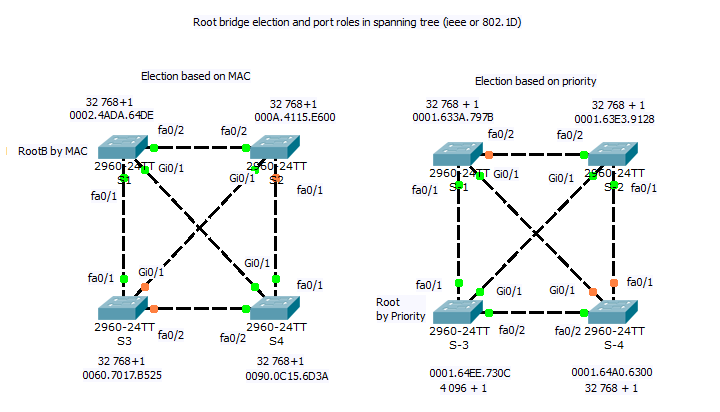
BPDU packets are propagated through the switches, each switch identifying itself with its BID or Bridge Identifier. The switch with the lowest Bridge Identifier will become the Root Switch. Default the Priority Field of the Bridge Identifier is 32768 which will lead to the switch with the lowest MAC address being the Root Switch.
BID or Bridge Identifier
The BID is a Integer consisting of eight Bytes. The first two bytes are priority and the remaining six bytes are the MAC address of the switch.
| 2 Bytes Priority | 6 Bytes MAC Address |
Extended System in Bridge ID field
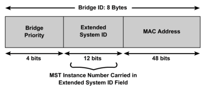
MAC address reduction splits the 16-bit field into two fields: a configurable 4-bit field and a nonconfigurable 12-bit field. The 12-bit field carries the VLAN ID (VID) or, with MSTP, the MSTP instance number. The two fields are merged to create the unique Bridge Priority field for a particular VLAN or MSTP instance. The appending MAC address remains the same for all instances. The priority field is default 32768.
| Priority 4 bits | Priority 16 bits | Actual MSTP Priority | Actual PVST/PVST+ Priority |
|---|---|---|---|
| 0 | 0 | 0 + MSTP instance | 0 + VLAN ID |
| 1 | 4096 | 4096 + MSTP instance | 4096 + VLAN ID |
| 2 | 8192 | 8192 + MSTP instance | 8192 + VLAN ID |
| 3 | 12288 | 12288 + MSTP instance | 12288 + VLAN ID |
| 4 | 16384 | 16384 + MSTP instance | 16384 + VLAN ID |
| 5 | 20480 | 20480 + MSTP instance | 20480 + VLAN ID |
| 6 | 24576 | 24576 + MSTP instance | 24576 + VLAN ID |
| 7 | 28672 | 28672 + MSTP instance | 28672 + VLAN ID |
| 8 | 32768 | 32768 + MSTP instance | 32768 + VLAN ID |
| 9 | 36864 | 36864 + MSTP instance | 36864 + VLAN ID |
| 10 | 40960 | 40960 + MSTP instance | 40960 + VLAN ID |
| 11 | 45056 | 45056 + MSTP instance | 45056 + VLAN ID |
| 12 | 49152 | 49152 + MSTP instance | 49152 + VLAN ID |
| 13 | 53248 | 53248 + MSTP instance | 53248 + VLAN ID |
| 14 | 57344 | 57344 + MSTP instance | 57344 + VLAN ID |
| 15 | 61440 | 61440 + MSTP instance | 61440 + VLAN ID |
Root Bridge Election graph
BPDU Packet
| Bytes | Field name | Notes |
|---|---|---|
| 2 | Protocol ID | Always 0 |
| 1 | Version | Always 0 |
| 1 | Message Type | Configuration or TCN BPPU |
| 1 | Flags | |
| 8 | Root Bridge ID | 2 Bytes priority and 6 Bytes MAC address |
| 4 | Path Cost | Cost of all links from the transmitting switch to the root bridge
See table below |
| 8 | Bridge ID | 2 Bytes priority and 6 Bytes MAC address |
| 2 | Port ID | Transmitting switch port ID |
| 2 | Message age | in 256's of a second |
| 2 | Max age | in 256's of a second |
| 2 | Hello Time | in 256's of a second |
| 2 | Forward delay | in 256's of a second |
BPDU Path Cost
| Link Bandwidth | Old STP Cost | New STP Cost |
|---|---|---|
| 4 Mbps | 250 | 250 |
| 10 Mbps | 100 | 100 |
| 16 Mbps | 63 | 62 |
| 45 Mbps | 22 | 39 |
| 100 Mbps | 10 | 19 |
| 622 Mbps | 2 | 6 |
| 1 Gbps | 1 | 4 |
| 10 Gbps | 0 | 2 |
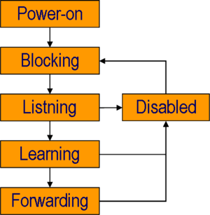
STP Port States
|
Enhancements to the Spanning Tree Protocol
- Spanning Tree protocol history
- Per VLAN Spanning Tree Protocol (PVST+)
- Rapid Spanning Tree Protocol (RSTP)
- Multiple Spanning Tree Protocol (MSTP)
- Per VLAN Rapid Spanning Tree (PVRST)
Der er adskillige tilføjelser til Ciscos implementering af STP heriblandt
PortFast
PortFast får et Lag 2 LAN interface til at skifte til forwarding tilstand straks. Dette foregår ved at springe over listening og learning og gå direkte til forwarding tilstand.
Anvend kun portfast på porten når den er tilsluttet en end-unit. (PC,Printer...)
AccessSW1#<input>configure terminal</input>
Enter configuration commands, one per line.  End with CNTL/Z.
AccessSW1(config)#<input>int range fastEthernet 0/1 - 24</input>
AccessSW1(config-if-range)#<input>spanning-tree portfast</input>
Eksempel på konfigurering af portfast
BPDU guard
Hvis BPDU guard er konfiguret på en PortFast enablet port, vil porten straks lukke ned hvis der kommer en BPDU ind.
AccessSW1#<input>configure terminal</input>
Enter configuration commands, one per line.  End with CNTL/Z.
AccessSW1(config)#<input>int range fastEthernet 0/1 - 24</input>
AccessSW1(config-if-range)#<input>spanning-tree portfast</input>
AccessSW1(config-if-range)#<input>spanning-tree bpduguard enable</input>
Uplinkfast
Giver tre til fem sekunders konvergens tid - det vil sige før linken er i drift igen - efter en link fejl. Dette foregår ved at springe over listening og learning og gå direkte til forwarding tilstand.
Anvend kun uplinkfast på links mellem switche som ikke er root-switchen.
Uplinkfast kan ligeledes load-balancing mellem redundante lag 2 links ved at anvende uplink groups.
En uplink group er en gruppe af porte der kører spanning tree i PVST - Per-Vlan Spanning Tree - hvor kun en port er i forwarding og resten er blocked. Load-Balancing kan opnås ved at have forskellige porte i forwarding hvor de andre er blocked
DistSW1#<input>configure terminal</input>
Enter configuration commands, one per line.  End with CNTL/Z.
DistSW1(config)#<input>spanning-tree uplinkfast</input>
UplinkFast enables globalt på switchen.
BackboneFast
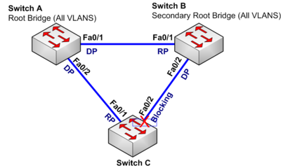
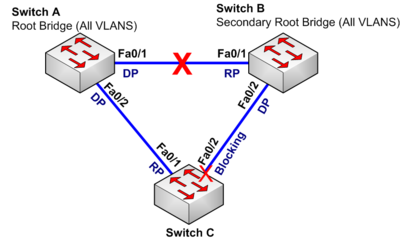
BackboneFast er en Cisco udvidelse til Spanning-Tree som anvendes i forbindelse med UplinkFast og nedsætter nedetiden på en switch der modtager BPDU'er fra en anden Switch som har mistet forbindelsen til Root-Switchen og selv tror den er Root-Switch. Se eksemplet herunder
| 1 |
Normal driftNetværket er stabilt og fungerer som tiltænkt. Switch-C er i Blocking state, fordi Switch-B har en bedre Bridge-ID end Switch-C. Switch-B er Secondary Root-Bridge. |
|
| 2 |
LinkfejlDer sker en linkfejl mellem Switch-A og Switch-B. Switch-B har nu mistet sin Root-port og tror nu at den er Root-Bridge, og begynder nu at sende sine egne BPDU pakker ud af Fa0/2. Switch-C modtager nu BPDU-pakker fra Switch-A og Switch-B. Pakkerne fra Switch-B har en dårligere Bridge-ID end dem fra Switch-A. BPDU-pakker sendes og modtages også igennem blockede porte. |
|
| 3 |
Normal Spanning-Tree uden BackboneFastUnder normal Spanning-Tree vil Switch-C ignorere BPDU-pakkerne fra Switch-B indtil Max-Age timeren udløber. (normalt 20 sekunder) Hvis den stadig modtager BPDU-pakker fra Switch-B vil Switch-C begynde at sende BPDU-pakkerne fra Switch-A ud på Fa0/2 til Switch-C. Fa0/2 vil herefter skifte til Listening tilstand (15 sekunder) og Learning tilstand (15 sekunder). I alt tager det Max-Age + Listening + Learning sekunder før netværket er i drift igen. 20 + 15 + 15 = 50 sekunder. |
|
| 4 |
Spanning-Tree med BackboneFastNår backboneFast er enablet på alle switche, vil Switch-C reagere anderledes end beskrevet ovenfor når den modtager BPDU pakker fra Switch B. Når Switch-C modtager en BPDU-pakke fra Switch-B tyder det på at Switch-B har tabt kontakten med Root-Brigden(Switch-A). Det kunne også betyde at Switch-C måske har mistet kontakten til Root-Brigden(Switch-A). Derfor vil Switch-C udsende RLQ (Root-Link Query) ud på alle porte som ikke er Designated-Ports(Upstream). I eksemplet udsender Switch-C RLQ pakker på port Fa0/1 til Switch-A. Switch-A - som er Root-Bridge og har enablet BackboneFast - sender Switch-A en RLQ response pakke tilbage til Switch-C. Denne pakke fortæller Switch-C at den stadig har kontakt med Root-Bridgen. Derfor behøver Switch-C ikke vente i Max-Age (20 sekunder) men kun at sende fa0/2 igennem Listening (15 sekunder) og Learning (15 sekunder) tilstandende. Nedetiden er hermed nedbragt fra 50 sekunder til 30 sekunder. |
DistSW1#<input>configure terminal</input>
Enter configuration commands, one per line.  End with CNTL/Z.
DistSW1(config)#<input>spanning-tree uplinkfast</input>
DistSW1(config)#<input>spanning-tree backbonefast</input>
Loop Guard
Loop-Guard forhindrer at en Alternate-Port eller Root-Port bliver en Designated-Port hvis BPDU'erne udebliver. Dette kan forhindre en Loop - og dermed en Broadcast-storm hvis der skulle opstå en unidirectional link. Se også UDLD herunder.
Dist-SW1#<input>configure terminal</input>
Enter configuration commands, one per line.  End with CNTL/Z.
Dist-SW1(config)#<input>interface gigabitEthernet 0/1</input>
Dist-SW1(config-if)#<input>spanning-tree guard loop</input>
Root Guard
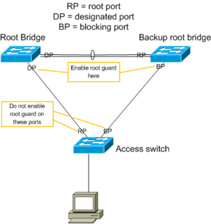
Root-Guard kan anvendes til at afvise en Switch som har en bedre Bridge-ID end den tiltænkte Root-Switch. Root-Guard tvinger en port til at være en Designated-port. Altså en port der vender væk fra Root-Brigden. Hvis der kommer en Switch med en bedre Bridge-ID end den rigtige Root-Switch vil porten lukke ned, og derved stoppe BPDU pakkerne fra den falske Root-Switch.
Dist-SW1#<input>configure terminal</input>
Enter configuration commands, one per line.  End with CNTL/Z.
Dist-SW1(config)#<input>interface gigabitEthernet 0/1</input>
Dist-SW1(config-if)#<input>spanning-tree guard root</input>
UDLD - Unidirectional Link Detection
UDLD overvåger den fysiske konfiguration af portene og opdager hvis en port har en en-vejs forbindelse - Unidirectional - og lukker porten ned.
Global enabling af UDLD
Dist-SW1#<input>configure terminal</input>
Enter configuration commands, one per line.  End with CNTL/Z.
Dist-SW1(config)#<input>udld enable</input>
Enabling af UDLD på interface
Dist-SW1#<input>configure terminal</input>
Enter configuration commands, one per line.  End with CNTL/Z.
Dist-SW1(config)#<input>interface gigabitEthernet 0/1</input>
Dist-SW1(config-if)#<input>udld enable</input>
MST: Multiple Spanning Tree protocol
Ved MST kan man definere flere Spanning Tree instancer. I eksemplet nedenunder er der defineret to MST instancer. Instans 1 bygger et spanning-tree for VLAN 10 til 50 og instans 2 bygger et spanning-tree for VLAN 51 til 99. For at load-balance mellem forskellige switche og trunks og for at få redundans er Switch 1 standard root-switch for instans 1 og Switch 2 standard root-switch for instans 2.
hostname Switch-1
spanning-tree mode mst
spanning-tree extend system-id
!
spanning-tree mst configuration
 name TEKKOM
 revision 1
 instance 1 vlan 10-50
 instance 2 vlan 51-99
!
spanning-tree mst 1 priority 24576
spanning-tree mst 2 priority 32768

!
vlan internal allocation policy ascending
hostname Switch-2
spanning-tree mode mst
spanning-tree extend system-id
!
spanning-tree mst configuration
name TEKKOM
revision 1
instance 1 vlan 10-50
instance 2 vlan 51-99
!
spanning-tree mst 1 priority 32768
spanning-tree mst 2 priority 24576
!
vlan internal allocation policy ascending


