Difference between revisions of "CCNP SWITCH/Implementing Inter-VLAN Routing"
m (→Inter-VLAN Routing Using SWI) |
m |
||
| (12 intermediate revisions by one other user not shown) | |||
| Line 1: | Line 1: | ||
| − | |||
=Inter-VLAN Routing= | =Inter-VLAN Routing= | ||
Because VLANs isolate trafficto a defined broadcast domain and subnet, network devices in different VLANs cannot communicate with each other natively. | Because VLANs isolate trafficto a defined broadcast domain and subnet, network devices in different VLANs cannot communicate with each other natively. | ||
| Line 96: | Line 95: | ||
Switch(config-if)# <input>ip address 10.20.1.1 255.255.255.0</input> | Switch(config-if)# <input>ip address 10.20.1.1 255.255.255.0</input> | ||
Switch(config-if)# <input>no shutdown</input> | Switch(config-if)# <input>no shutdown</input> | ||
| + | </source> | ||
| + | ===SVI Autostate=== | ||
| + | SVi interfaces are consideres up if: | ||
| + | *The VLAN exists and is active in the VLAN database on the switch. | ||
| + | *The VLAN interface exists and is not administratively down. | ||
| + | *At least one Layer 2 (access or trunk) port exists on the switch, has a link in the up state on this VLAN, and is in the spanning-tree forwarding state on the VLAN. | ||
| + | Disable autostate | ||
| + | <source lang=cli> | ||
| + | Switch(config)# <input>interface gigabitEthernet0/1</input> | ||
| + | Switch(config-if)# <input>switchport autostate exclude</input> | ||
</source> | </source> | ||
| Line 102: | Line 111: | ||
Configuring a routed port | Configuring a routed port | ||
<source lang=cli> | <source lang=cli> | ||
| − | Switch(config)#interface fastethernet 0/1 | + | Switch(config)#<input>interface fastethernet 0/1</input> |
| − | Switch(config-if)#no switchport | + | Switch(config-if)#<input>no switchport</input> |
| − | Switch(config-if)#ip address 192.168.1.1 255.255.255.0 | + | Switch(config-if)#<input>ip address 192.168.1.1 255.255.255.0</input> |
| − | Switch(config-if)#no shutdown | + | Switch(config-if)#<input>no shutdown</input> |
| + | </source> | ||
| + | ==Configure Layer 3 EtherChannel== | ||
| + | It is important to match the EtherChannel configuration on both sides on the switches, and the IP addresses on the Portchannel Interfaces should be on the same sub-nets/VLAN to communicate. | ||
| + | <source lang=cli> | ||
| + | switch(config)#<input> interface fastethernet 0/23</input> | ||
| + | switch(config-if)# <input>no switchport</input> | ||
| + | switch(config-if)#<input> channel-group 1 mode on</input> | ||
| + | switch(config)# <input>interface fastethernet 0/24</input> | ||
| + | switch(config-if)# <input>no switchport</input> | ||
| + | switch(config-if)# <input>channel-group 1 mode on</input> | ||
| + | switch(config)# <input>interface port-channel 1</input> | ||
| + | switch(config-if)# <input>no switchport</input> | ||
| + | switch(config-if)# <input>ip address 10.1.20.1 255.255.255.0</input> | ||
</source> | </source> | ||
| + | ==Multilayer Switch Routing Protocol configuration== | ||
| + | <source lang=cli> | ||
| + | Switch(config)#<input> ip routing</input> | ||
| + | Switch(config)# <input>router eigrp 100</input> | ||
| + | Switch(config-router)#<input> no auto-summary</input> | ||
| + | Switch(config-router)# <input>network 10.0.0.0</input> | ||
| + | Switch(config-router)# <input>passive-interface default</input> | ||
| + | Switch(config-router)# <input>no passive-interface fa0/24</input> | ||
| + | Switch(config)#<input> interface f0/24</input> | ||
| + | Switch(config-if)# <input>description Uplink</input> | ||
| + | Switch(config-if)# <input>ip summary-address eigrp 100 10.1.0.0 255.255.240.0</input> | ||
| + | </source> | ||
| + | =Implementing Dunamic Host Configuration Protocol in a Multilayer Switched Environment= | ||
| + | As defined in RFC 2131, Dynamic Host Configuration Protocol (DHCP) provides configuration parameters to Internet hosts. | ||
| + | {| | ||
| + | |[[Image:ScreenShot1108.jpg|800px|left|thumb|External DHCP Server]] | ||
| + | |} | ||
| + | {| | ||
| + | |[[Image:ScreenShot1110.jpg|800px|left|thumb|DHCP DORA]] | ||
| + | |} | ||
| + | Multilayer Switch Configuration Example | ||
| + | <source lang=cli> | ||
| + | Switch(config)# <input>ip dhcp excluded-address 10.1.10.1 10.1.10.20</input> | ||
| + | Switch(config)# <input>ip dhcp pool VLAN10</input> | ||
| + | Switch(config-dhcp)# <input>network 10.1.10.0 255.255.255.0</input> | ||
| + | Switch(config-dhcp)# <input>default-router 10.1.10.1</input> | ||
| + | Switch(config-dhcp)# <input>option 150 10.1.1.50</input> | ||
| + | Switch(config-dhcp)# <input>lease 0 8 0</input> | ||
| + | Switch(config-dhcp)# ! 0 days 8 hours 0 minutes | ||
| + | Switch(config)#<input> interface vlan10</input> | ||
| + | Switch(config-if)#<input> ip address 10.1.10.1 255.255.255.0</input> | ||
| + | </source> | ||
| + | ==Configure DHCP Relay== | ||
| + | To relay breadcast DHCP messages from the local subnet to the DHCP server an DHCP relay mechanism is use in Cisco IOS. The DHCP broadcast message is replayed from the switch as a unicast to the DHCP server and back again to the switch. The switch then broadcasts the message on to the local subnet. | ||
| + | {| | ||
| + | |[[Image:ScreenShot1111.jpg|800px|left|thumb|DHCP Relay]] | ||
| + | |} | ||
| + | <source lang=cli> | ||
| + | Switch(config)# <input>interface vlan10</input> | ||
| + | Switch(config-if)# <input>ip address 10.1.10.1 255.255.255.0</input> | ||
| + | Switch(config-if)# <input>ip helper-address 10.1.100.1</input> | ||
| + | </source> | ||
| + | ==Verify DHCP Operation== | ||
| + | <source lang=cli> | ||
| + | switch#<input> show ip dhcp binding</input> | ||
| + | Bindings from all pools not associated with VRF: | ||
| + | IP address Client-ID/ Lease expiration Type | ||
| + | Hardware address/ | ||
| + | User name | ||
| + | 10.1.10.21 0100.1bd5.132a.d2 Jun 25 2009 06:09 AM Automatic | ||
| + | 10.1.10.22 0100.4096.a46a.90 Jun 25 2009 09:40 AM Automatic | ||
| + | 10.1.10.23 0100.4096.aa98.95 Jun 25 2009 11:28 AM Automatic | ||
| + | </source> | ||
| + | <source lang=cli> | ||
| + | switch#<input> debug ip dhcp server packet</input> | ||
| + | DHCPD: DHCPDISCOVER received from client 0100.1bd5.132a.d2 on interface Vlan6. | ||
| + | DHCPD: Sending DHCPOFFER to client 0100.1bd5.132a.d2 (10.1.10.21). | ||
| + | DHCPD: broadcasting BOOTREPLY to client 001b.d513.2ad2. | ||
| + | DHCPD: DHCPREQUEST received from client 0100.1bd5.132a.d2. | ||
| + | DHCPD: Sending DHCPACK to client 0100.1bd5.132a.d2 (10.1.10.21). | ||
| + | DHCPD: broadcasting BOOTREPLY to client 001b.d513.2ad2. | ||
| + | </source> | ||
| + | =Deploying CEF-Based Multilayer Switching= | ||
| + | Layer 3 switching provides a wire-speed mechanism by which to route packets between VLANs using tables that store Layer2 and Layer3 forwarding information in the hardware.<br/><br/> | ||
| + | A Layer 3 switch performs three major functions: | ||
| + | *Packet Switching | ||
| + | *Route Processing | ||
| + | *Intelligent network services | ||
| + | Frame Rewrite: | ||
| + | {| | ||
| + | |[[Image:ScreenShot386.jpg|800px|left|thumb|Checksum calculation and rewrite.]] | ||
| + | |} | ||
| + | ==CAM and TCAM Tables== | ||
| + | ;CAM table | ||
| + | :The primary table used to make Layer 2 forwarding decisions. The table is built by recording the source MAC address and inbound port of all incoming frames. When a frame arrives at the switch with a destination MAC address of an entry in the CAM table, the frame is forwarded out through only the port that is associated with that specific MAC address. | ||
| + | {| | ||
| + | |[[Image:ScreenShot387.jpg|800px|left|thumb|CAM]] | ||
| + | |} | ||
| + | ;TCAM table | ||
| + | :Stores ACL, QoS, and other information generally associated with Layer 3 and up layer processing. | ||
| + | {| | ||
| + | |[[Image:ScreenShot388.jpg|800px|left|thumb|TCAM]] | ||
| + | |} | ||
| + | ===TCAM Layout=== | ||
| + | The TCAM is devided into several regions such as one for ACL, one for multicast and one for IP-PREFIX.<br/><br/> | ||
| + | The regions have these lookup types: | ||
| + | ;Exact-match region | ||
| + | :Consistsof Layer 3 entries for regions such as IP adjacencies. IP adjacencies are the next-hop information (MAC address) for an IP address. Other examples of exact-match regions are Layer 2 switching tables and UDP flooding tables. | ||
| + | ;Longest-match region | ||
| + | :Consistsof multiple “buckets” or groups of Layer 3 address entries organized in decreasing order by mask length. All entries within a bucket share the same mask value and key size. The buckets change their size dynamically by borrowing address entries from neighboring buckets. Although the size of the whole protocol region is fixed, as mentioned in Table 4-4, several platforms support configuration of the region size. For most platforms, the reconfigured size of the protocol region is effective only after the next system reboot. | ||
| + | ;First-match region | ||
| + | :Consists of regions that stop lookups after the first match of the entry. An example of when a first-match region is used is for ACL entries. | ||
| + | |||
| + | {| class="wikitable sortable" style="text-align:center" border=1 | ||
| + | |+ Common TCAM Protocol Regions | ||
| + | |- bgcolor=lightgrey | ||
| + | ! Region name !! Cisco IOS Region Name !! Lookup Type !! Key Size !! Sample result | ||
| + | |- | ||
| + | | IP adjacency || ip-adjacency || Exact-Match || 32 bits || MAC address rewrite information | ||
| + | |- | ||
| + | | IP prefix || ip-prefix || Longest-match || 32 bits || Next-hop routing information | ||
| + | |- | ||
| + | | IP multicast || ip-mcast || Longest match || 64 bits || Next-hop Routing information | ||
| + | |- | ||
| + | | Layer 2 switching || l2-switching || Exact-match || 64 bits || Destination interface and VLAN | ||
| + | |- | ||
| + | | UDP flooding || udp-flooding || Exact-match || 64 bits || Next-hop routing og MAC address rewrite information | ||
| + | |- | ||
| + | |Access lists || access-list || First-match || 128 bits || Permit, deny, or wildcard | ||
| + | |} | ||
| + | |||
| + | ==Distributed Hardware Forwarding== | ||
| + | {| | ||
| + | |[[Image:ScreenShot392.jpg|800px|left|thumb|hardware forwarding overview]] | ||
| + | |} | ||
| + | ==Cisco Switching Methods== | ||
| + | ;Process Switching | ||
| + | :In process switching, the router strips off the Layer 2 header for each incoming frame, looks up the Layer 3 destination network address in the routing table for each packet. | ||
| + | ;Fast Switching | ||
| + | :After the lookup of the first packet destined for a particular IP network, the router initializes the fast-switching cache used by the Fast switching mode. | ||
| + | ;Cisco Express Forwarding (CEF) | ||
| + | :The default-switching mode. CEF is less CPU-intensive than fast switching or process switching. | ||
| + | ===CEF modes of operation=== | ||
| + | *Central CEF mode | ||
| + | *Distributed CEF mode(dCEF) | ||
| + | ==CEF Processing== | ||
| + | {| | ||
| + | |[[Image:ScreenShot1112.jpg|800px|left|thumb|CEF]] | ||
| + | |} | ||
| + | The FIB contains a pointer to the Adjacency table with rewrite information.<br/> | ||
| + | The point could also point to these special adjacencies: | ||
| + | ;Punt adjacency | ||
| + | :Usedfor packets that require special handling by the Layer 3 engine or for features that are not yet supported by hardware switching. | ||
| + | ;Drop or discard adjacency | ||
| + | :Used to drop ingress packets. | ||
| + | ;Null adjacency | ||
| + | :Used to drop packets destined for a Null0 interface. The use of a Null0 interface is for access filtering of specific source IP packets. | ||
| + | ;Glean adjacency | ||
| + | :When no rewrite information exists the switch needs to make an ARP. | ||
| + | ==ARP Throttling== | ||
| + | he ARP throttling adjacency drops the first packet in any communication between due to ARP processing when no ARP entries exist for the Hosts. | ||
| + | =CEF Troubleshooting= | ||
| + | show ip cef vlan 10 detail<br/> | ||
| + | show adjacency<br/> | ||
| + | show adjacency gigabitethernet 1/5 detail<br/> | ||
| + | {{Source cli}} | ||
| + | [[Category:Cisco]][[Category:CCNP]] | ||
Latest revision as of 08:24, 13 November 2011
Contents
Inter-VLAN Routing
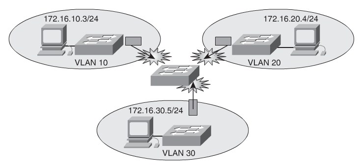
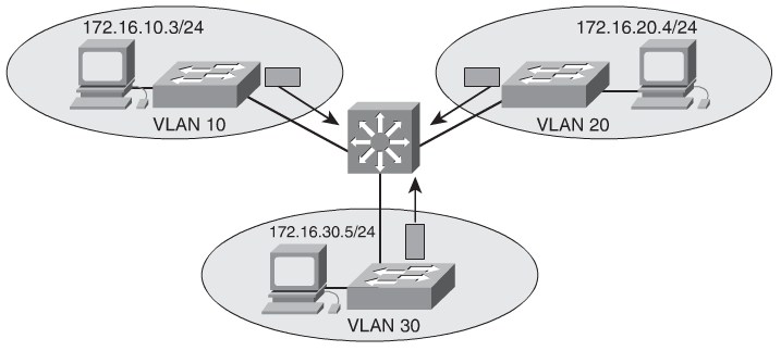
Because VLANs isolate trafficto a defined broadcast domain and subnet, network devices in different VLANs cannot communicate with each other natively.
Adding an external routing with subinterface routing does not scale beyond 50 VLANs. Cisco IOS routers only support trunking in IP Plus Feature set and above.
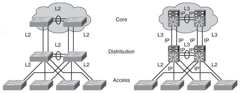
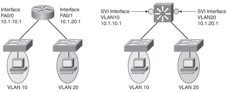
Catalyst Multilayer Switches support 3 different routed interface types:
- Routed Port
- A pure Layer 3 interface similar to a routed port on a Cisco IOS router.
- Switched Virtual Interface (SVI)
- A virtual VLAN interface for inter-VLAN routing. In other words, SVIs are the virtual routed VLAN interfaces.
- Bridged Virtual Interfaces (BVI)
- A Layer 3 virtual bridging interface.
All Cisco Layer 3 Switches support routing protocols, but several models requires enhanced software for specific routing protocol features.
To change between routed and switchports use no switchport and switchport interface commands respectively. Catalyst 6500 switches use L3 interfaces by default, so depending on the switching model the swithport and no switchport command might be present in the running-config files.
| Switch Type | Inter-VLAN Routing Capability | Inter-VLAN Routing Solution |
|---|---|---|
| Catalyst 2940/2950/2955/2960/2970 | No | N/A |
| Catalyst 3560/3750/3760 | Yes | Integrated |
| Catalyst 4000/4500/4948 | Yes | Catalyst 4000 running Cisco CatOS with Supervisor I or II, using the Layer 3 module, WS-X4232-L3 Catalyst 4000 with a Supervisor II+, III, IV, or V running Cisco IOS using integrated routing |
| Catalyst 6500 | Yes | Catalyst 6500 with an MSFC, MSFC II, or MSFC III daughter card running Cisco CatOS on the supervisors and Cisco IOS on the MSFC Catalyst 6500 with MSFC, MSFC II, or MSFC III running Cisco Native IOS Catalyst 6500 using a legacy MSM module |
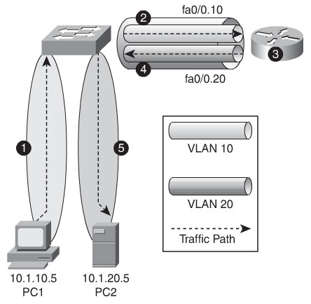
Router-on-a-Stick
Router-on-a-Stick Advantages and Disanvantages
- Works on any L2 switch that support Trunking.
- Simpel Implementation. Only one swithc port and one router interface require configuration.
- The Router provides Inter-VLAN Routing i a Layer 2 network.
- The Router is a single point of failure.
- Trunk link may be congested when multible VLANs use it.
- Latency might be higher as frames leave and re-enter the switch chassis multiple times and the router makes software-based routing decisions.
Router(config)# interface FastEthernet0/0
Router(config-if)#no shutdown
Router(config-if)#no ip address
Router(config)# interface FastEthernet 0/0.1
Router(config-subif)# description VLAN 1
Router(config-subif)# encapsulation dot1Q 1 native
Router(config-subif)# ip address 10.1.1.1 255.255.255.0
Router(config-subif)# exit
Router(config)# interface FastEthernet 0/0.2
Router(config-subif)# description VLAN 2
Router(config-subif)# encapsulation dot1Q 2
Router(config-subif)# ip address 10.2.2.1 255.255.255.0
Router(config-subif)# exit
Router(config)# end
!! Switch Configuration  **************************
switch(config)# interface FastEthernet 0/24
switch(config-if)# switchport trunk encapsulation dot1q
switch(config-if)# switchport mode trunk
switch(config-if)# end
Inter-VLAN Routing Using SWI
A long time ago high performance network consisted of L2 Switches. Routers routed i software and performed slow whereas switches switched in hardware.
As networks evolved routing became faster and got implemented in ASICs. Routing in hardware performs at wire-speed in most L3 Switches.
The number of Switch Virtual Interfaces a Layer 3 Switch support is not the same at the number of VLAN supported.
SVI is use to:
- Provide gateways for VLAN Clients
- Provide Layer 3 IP connectivity to the switch
- Support Routing Protocols
SVI: Advantages and Disadvantages:
- It is much faster than router-on-a-stick because everything is hardware switched and routed.
- No need for external links from the switch to the router for routing.
- Not limited to one link. Layer 2 EtherChannels can be used between the switches to get more bandwidth.
- Latency is much lower because it doesn’t need to leave the switch.
- It needs a Layer 3 switch to perform Inter-VLAN routing, which is more expensive.
Configure SVI inter-VLAN Routing
Switch# <input>configure terminal</input>
Enter configuration commands, one per line.  End with CNTL/Z.
Switch(config)# <input>ip routing</input>
Switch(config)# <input>interface vlan 10</input>
Switch(config-if)# <input>ip address 10.10.1.1 255.0.0.0</input>
Switch(config-if)# <input>no shutdown</input>
Switch(config-if)# <input>exit</input>
Switch(config)# <input>interface vlan20</input>
Switch(config-if)# <input>ip address 10.20.1.1 255.255.255.0</input>
Switch(config-if)# <input>no shutdown</input>
SVI Autostate
SVi interfaces are consideres up if:
- The VLAN exists and is active in the VLAN database on the switch.
- The VLAN interface exists and is not administratively down.
- At least one Layer 2 (access or trunk) port exists on the switch, has a link in the up state on this VLAN, and is in the spanning-tree forwarding state on the VLAN.
Disable autostate
Switch(config)# <input>interface gigabitEthernet0/1</input>
Switch(config-if)# <input>switchport autostate exclude</input>
Routing with Routed Ports
Routed interfaces don’t support subinterfaces as with Cisco IOS routers. But it is possible to configure a routed EtherChannel. Routed ports removes Layer 2 protocols such as STP and VTP.
Configuring a routed port
Switch(config)#<input>interface fastethernet 0/1</input>
Switch(config-if)#<input>no switchport</input>
Switch(config-if)#<input>ip address 192.168.1.1 255.255.255.0</input>
Switch(config-if)#<input>no shutdown</input>
Configure Layer 3 EtherChannel
It is important to match the EtherChannel configuration on both sides on the switches, and the IP addresses on the Portchannel Interfaces should be on the same sub-nets/VLAN to communicate.
switch(config)#<input> interface fastethernet 0/23</input>
switch(config-if)# <input>no switchport</input>
switch(config-if)#<input> channel-group 1 mode on</input>
switch(config)# <input>interface fastethernet 0/24</input>
switch(config-if)# <input>no switchport</input>
switch(config-if)# <input>channel-group 1 mode on</input>
switch(config)# <input>interface port-channel 1</input>
switch(config-if)# <input>no switchport</input>
switch(config-if)# <input>ip address 10.1.20.1 255.255.255.0</input>
Multilayer Switch Routing Protocol configuration
Switch(config)#<input> ip routing</input>
Switch(config)# <input>router eigrp 100</input>
Switch(config-router)#<input> no auto-summary</input>
Switch(config-router)# <input>network 10.0.0.0</input>
Switch(config-router)# <input>passive-interface default</input>
Switch(config-router)# <input>no passive-interface fa0/24</input>
Switch(config)#<input> interface f0/24</input>
Switch(config-if)# <input>description Uplink</input>
Switch(config-if)# <input>ip summary-address eigrp 100 10.1.0.0 255.255.240.0</input>
Implementing Dunamic Host Configuration Protocol in a Multilayer Switched Environment
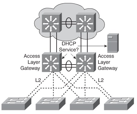
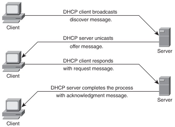
As defined in RFC 2131, Dynamic Host Configuration Protocol (DHCP) provides configuration parameters to Internet hosts.
Multilayer Switch Configuration Example
Switch(config)# <input>ip dhcp excluded-address 10.1.10.1 10.1.10.20</input>
Switch(config)# <input>ip dhcp pool VLAN10</input>
Switch(config-dhcp)# <input>network 10.1.10.0 255.255.255.0</input>
Switch(config-dhcp)# <input>default-router 10.1.10.1</input>
Switch(config-dhcp)# <input>option 150 10.1.1.50</input>
Switch(config-dhcp)# <input>lease 0 8 0</input>
Switch(config-dhcp)# ! 0 days 8 hours 0 minutes
Switch(config)#<input> interface vlan10</input>
Switch(config-if)#<input> ip address 10.1.10.1 255.255.255.0</input>
Configure DHCP Relay
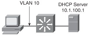
To relay breadcast DHCP messages from the local subnet to the DHCP server an DHCP relay mechanism is use in Cisco IOS. The DHCP broadcast message is replayed from the switch as a unicast to the DHCP server and back again to the switch. The switch then broadcasts the message on to the local subnet.
Switch(config)# <input>interface vlan10</input>
Switch(config-if)# <input>ip address 10.1.10.1 255.255.255.0</input>
Switch(config-if)# <input>ip helper-address 10.1.100.1</input>
Verify DHCP Operation
switch#<input> show ip dhcp binding</input>
Bindings from all pools not associated with VRF:
IP address  Client-ID/        Lease expiration      Type
Hardware address/
User name
10.1.10.21  0100.1bd5.132a.d2  Jun 25 2009 06:09 AM  Automatic
10.1.10.22  0100.4096.a46a.90  Jun 25 2009 09:40 AM  Automatic
10.1.10.23  0100.4096.aa98.95  Jun 25 2009 11:28 AM  Automatic
switch#<input> debug ip dhcp server packet</input>
DHCPD: DHCPDISCOVER received from client 0100.1bd5.132a.d2 on interface Vlan6.
DHCPD: Sending DHCPOFFER to client 0100.1bd5.132a.d2 (10.1.10.21).
DHCPD: broadcasting BOOTREPLY to client 001b.d513.2ad2.
DHCPD: DHCPREQUEST received from client 0100.1bd5.132a.d2.
DHCPD: Sending DHCPACK to client 0100.1bd5.132a.d2 (10.1.10.21).
DHCPD: broadcasting BOOTREPLY to client 001b.d513.2ad2.Deploying CEF-Based Multilayer Switching
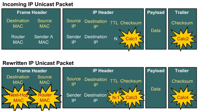
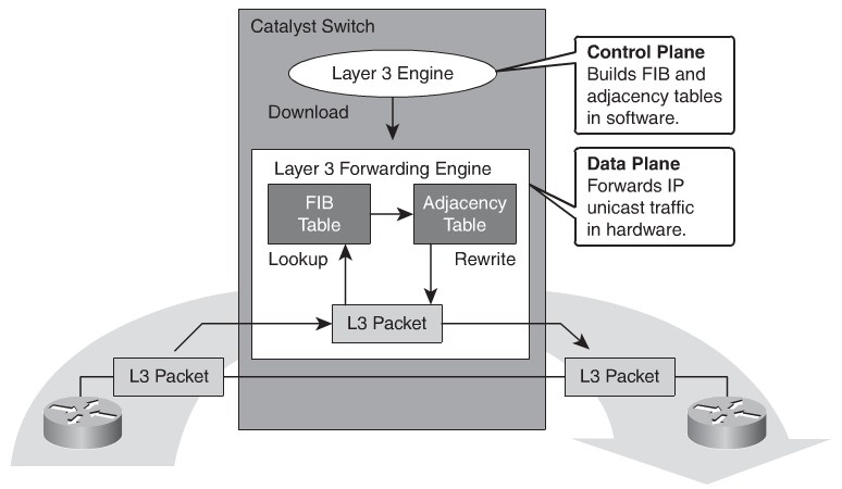
Layer 3 switching provides a wire-speed mechanism by which to route packets between VLANs using tables that store Layer2 and Layer3 forwarding information in the hardware.
A Layer 3 switch performs three major functions:
- Packet Switching
- Route Processing
- Intelligent network services
Frame Rewrite:
CAM and TCAM Tables
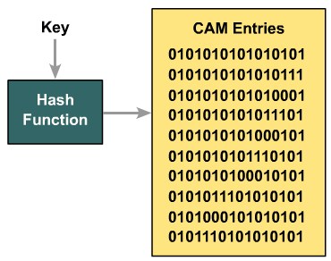
- CAM table
- The primary table used to make Layer 2 forwarding decisions. The table is built by recording the source MAC address and inbound port of all incoming frames. When a frame arrives at the switch with a destination MAC address of an entry in the CAM table, the frame is forwarded out through only the port that is associated with that specific MAC address.
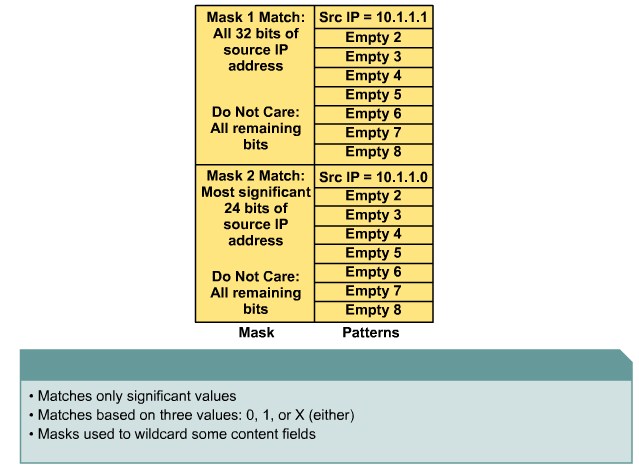
- TCAM table
- Stores ACL, QoS, and other information generally associated with Layer 3 and up layer processing.
TCAM Layout
The TCAM is devided into several regions such as one for ACL, one for multicast and one for IP-PREFIX.
The regions have these lookup types:
- Exact-match region
- Consistsof Layer 3 entries for regions such as IP adjacencies. IP adjacencies are the next-hop information (MAC address) for an IP address. Other examples of exact-match regions are Layer 2 switching tables and UDP flooding tables.
- Longest-match region
- Consistsof multiple “buckets” or groups of Layer 3 address entries organized in decreasing order by mask length. All entries within a bucket share the same mask value and key size. The buckets change their size dynamically by borrowing address entries from neighboring buckets. Although the size of the whole protocol region is fixed, as mentioned in Table 4-4, several platforms support configuration of the region size. For most platforms, the reconfigured size of the protocol region is effective only after the next system reboot.
- First-match region
- Consists of regions that stop lookups after the first match of the entry. An example of when a first-match region is used is for ACL entries.
| Region name | Cisco IOS Region Name | Lookup Type | Key Size | Sample result |
|---|---|---|---|---|
| IP adjacency | ip-adjacency | Exact-Match | 32 bits | MAC address rewrite information |
| IP prefix | ip-prefix | Longest-match | 32 bits | Next-hop routing information |
| IP multicast | ip-mcast | Longest match | 64 bits | Next-hop Routing information |
| Layer 2 switching | l2-switching | Exact-match | 64 bits | Destination interface and VLAN |
| UDP flooding | udp-flooding | Exact-match | 64 bits | Next-hop routing og MAC address rewrite information |
| Access lists | access-list | First-match | 128 bits | Permit, deny, or wildcard |
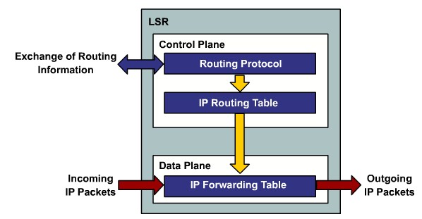
Distributed Hardware Forwarding
Cisco Switching Methods
- Process Switching
- In process switching, the router strips off the Layer 2 header for each incoming frame, looks up the Layer 3 destination network address in the routing table for each packet.
- Fast Switching
- After the lookup of the first packet destined for a particular IP network, the router initializes the fast-switching cache used by the Fast switching mode.
- Cisco Express Forwarding (CEF)
- The default-switching mode. CEF is less CPU-intensive than fast switching or process switching.
CEF modes of operation
- Central CEF mode
- Distributed CEF mode(dCEF)
CEF Processing
The FIB contains a pointer to the Adjacency table with rewrite information.
The point could also point to these special adjacencies:
- Punt adjacency
- Usedfor packets that require special handling by the Layer 3 engine or for features that are not yet supported by hardware switching.
- Drop or discard adjacency
- Used to drop ingress packets.
- Null adjacency
- Used to drop packets destined for a Null0 interface. The use of a Null0 interface is for access filtering of specific source IP packets.
- Glean adjacency
- When no rewrite information exists the switch needs to make an ARP.
ARP Throttling
he ARP throttling adjacency drops the first packet in any communication between due to ARP processing when no ARP entries exist for the Hosts.
CEF Troubleshooting
show ip cef vlan 10 detail
show adjacency
show adjacency gigabitethernet 1/5 detail
