Difference between revisions of "Enterprise Data Center Design"
m |
m (→Lag 2 - Looped design) |
||
| Line 69: | Line 69: | ||
|- | |- | ||
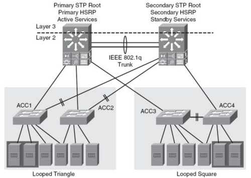
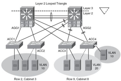
|[[Image:Data Center Lag 2 looped Square Access.png|400px|thumb| Looped design Square Access]] | |[[Image:Data Center Lag 2 looped Square Access.png|400px|thumb| Looped design Square Access]] | ||
| + | |- | ||
|[[Image:Data Center Lag 2 looped Triangle Access.png|400px|thumb| Looped design Triangle Access]] | |[[Image:Data Center Lag 2 looped Triangle Access.png|400px|thumb| Looped design Triangle Access]] | ||
|} | |} | ||
| + | |||
== Lag 2 - Loop frit design == | == Lag 2 - Loop frit design == | ||
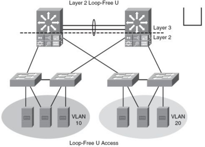
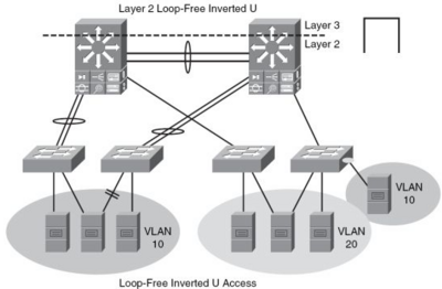
I Lag to Loop frit design er der ikke VLAN på Aggregationslaget modsat Looped design (Se overnfor). Ved omvendt U er det dog muligt at have VLAN på Aggregationslaget. Lag to services er supporteret. Lag tre Routning foregår på Aggregations laget. | I Lag to Loop frit design er der ikke VLAN på Aggregationslaget modsat Looped design (Se overnfor). Ved omvendt U er det dog muligt at have VLAN på Aggregationslaget. Lag to services er supporteret. Lag tre Routning foregår på Aggregations laget. | ||
Latest revision as of 07:24, 27 August 2012
Kapitel 5 fra CCDP ARCH bogen.
Contents
- 1 This article is under development....
- 2 Designing The Core and Aggregation Layers
- 3 Data Center Core layer design
- 4 Aggregation Layer
- 5 Spanning tree design
- 6 Access Lag
- 6.1 Lag 2 - Looped design
- 6.2 Lag 2 - Loop frit design
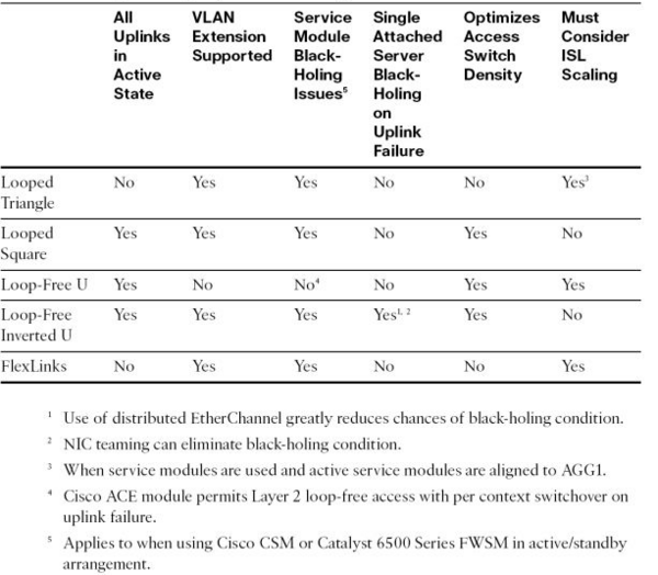
- 6.3 Sammenligning af lag to Access designs
- 6.4 Lag 3 på Access laget
- 6.5 6500 Services Module Placement Considerations
- 6.6 Optimizing EtherChannel U tilization with Min-Links
- 6.7 STP in the DataCenter
- 6.8 Cabinet Design with 1RU Switching
- 6.9 Cabinet Design with Modular Access Switches
- 6.10 Hybrid Design With OOB Switches
- 6.11 High Availability and Failover Times
- 6.12 High Availability and Cisco NSF with SSO
- 7 Eksterne henvisninger
Designing The Core and Aggregation Layers
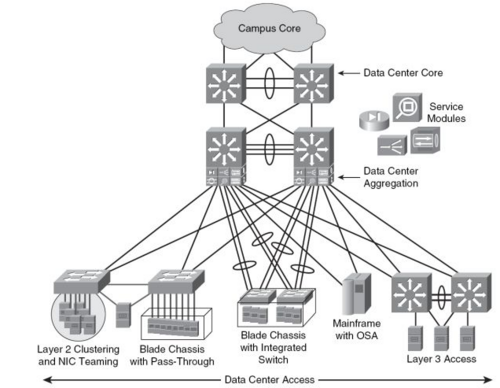
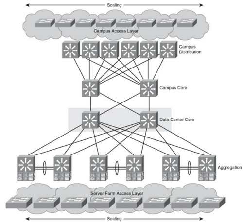
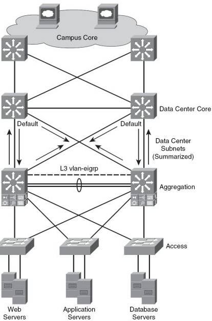
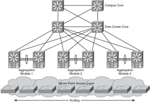
Data Center arkitekturen er baseret på en tre lags model.
- Core laget består af høj-hastigheds OSI lag 3.
- Aggregation laget forbinder Access-Laget med enten OSI lag 2 eller OSI lag 3.
- Access Laget giver fysisk forbindelse til Serverne.
fordele ved tre-lags modellen
- Hvis det er nødvendigt at samme VLAN skal være på flere Access Switche samtidig kan Aggregation-Switchene-----
Data Center Core layer design
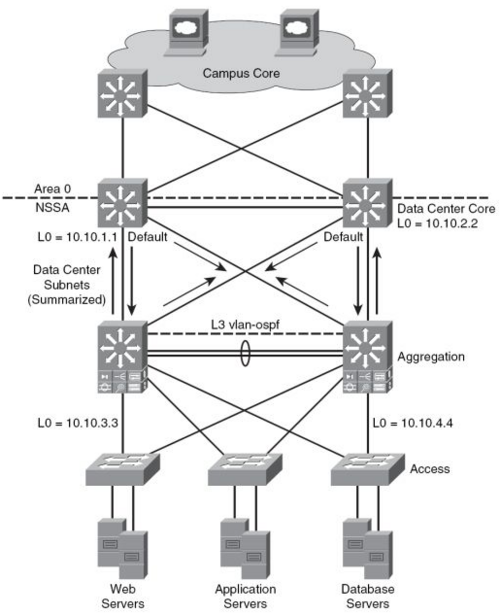
Routnings Protokoller
OSPF
EIGRP
Aggregation Layer
Spanning tree design
Cisco anbefaler at benytte sig af RPVST+.
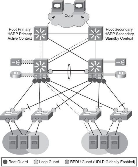
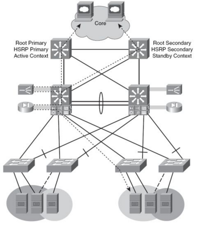
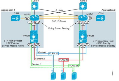
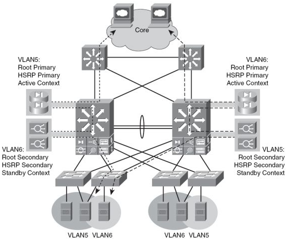
Aktiv STP,HSRP og Service Context Alignment
Active/Standby Service Module Design
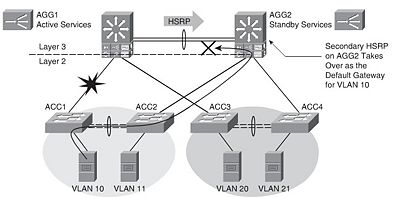
I tegningen herunder er den ene Aggregation Switch Active og den anden Standby for al trafikken fra Access laget.
- Cisco 6500 med FSWM 2.x
Active/Active Service Module Design
I tegningen herunder er begge Aggregation Switche Active for hver deres VLAN's.
- Cisco 6500 med FSWM 3.1
|
Establisheing Inbound Path Preference
Route Health Injection(RHI) tillader at en Cisco CSM/ACE i en 6500 switch installerer en hoste route til den virtuelle server. /32 routen fjerner problemer med asymmetriske routing.
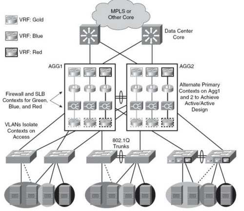
Anvendelse af VRF (MPLS) i Data centeret
Access Lag
Lag 2 - Looped design
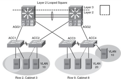
I Lag to Looped Design er VLAN's termineret i Aggregation laget og Lag 2 services som NIC teaming, Clustering og Statefull Services som for eksempel Firewall, Server Load Balancing, SSL kan udføres på ISO lag 2. Lag tre Routning foregår på Aggregations laget.
Lag 2 - Loop frit design
I Lag to Loop frit design er der ikke VLAN på Aggregationslaget modsat Looped design (Se overnfor). Ved omvendt U er det dog muligt at have VLAN på Aggregationslaget. Lag to services er supporteret. Lag tre Routning foregår på Aggregations laget.
Sammenligning af lag to Access designs
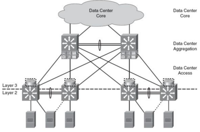
Lag 3 på Access laget
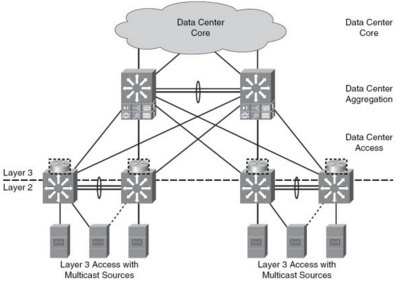
Statefull Services som kræver lag to konnektivitet kan ikke udføres af Aggregationslaget hvis Lag tre Routning foregår på Access-laget.
Multicast Source Support
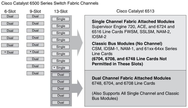
6500 Services Module Placement Considerations
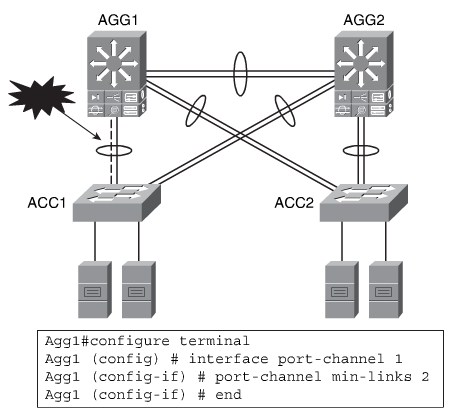
Optimizing EtherChannel U tilization with Min-Links
STP in the DataCenter
RPVST+ is the most common STP used in the data center today, and is the implementation recommended by Cisco for the enterprise data center.
- It scales to a large size (about 10,000 logical ports).
- Coupled with UDLD, loop guard, root guard, and BPDU guard, it provides a strong and stable Layer 2 design solution.
- It is a proven solution that is easy to implement and scale.
MST is not as common in the enterprise data center because of its characteristics:
- It permits large-scale STP implementations (about 30,000 logical ports). This is typically more useful for service providers and application service providers.
- It isn’t as flexible as RPVST+.
- It has service module implications for firewalls in transparent mode.
- It is more commonly used with service providers and application service providers.
Limit HSRP instances: The number of VLANs is typically tied to the number of
HSRP instances. Cisco recommends a maximum of 500 HSRP instances on the Catalyst 6500 series Supervisor Engine 720 with default timers.
Use MST if it meets the requirements: If you cannot support the STP scaling issues with RSTP, you can consider implementing MST.
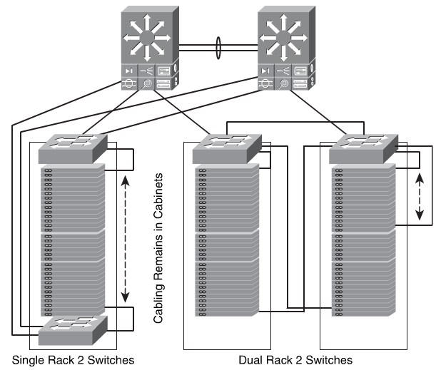
Cabinet Design with 1RU Switching
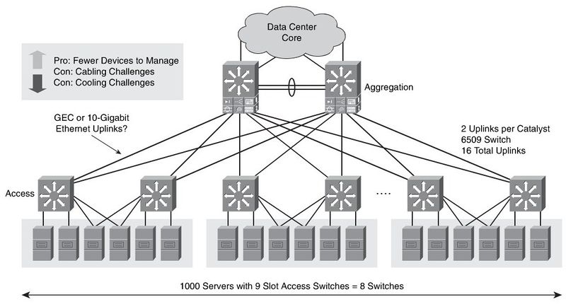
Cabinet Design with Modular Access Switches
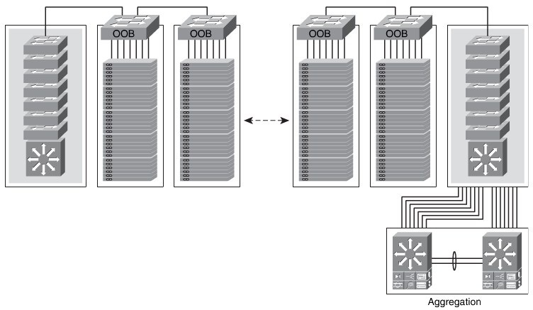
Hybrid Design With OOB Switches
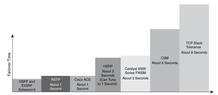
High Availability and Failover Times
High Availability and Cisco NSF with SSO
This convergence time and possible lost sessions can be avoided by using dual Catalyst 6500 series Supervisor Engine 720 engines and Cisco NSF with SSO on the primary aggregation switch of the data center.
 This article is under development....