Difference between revisions of "Spanning tree"
m (→STP Port States) |
m (→STP Port States) |
||
| Line 115: | Line 115: | ||
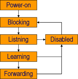
*Learning state (forward delay = 15 sek.) | *Learning state (forward delay = 15 sek.) | ||
**Listening for BPDU’s | **Listening for BPDU’s | ||
| − | **Data packets are | + | **Data packets ''are received'' to learn MAC addresses. |
**Data packets are not transmitted. | **Data packets are not transmitted. | ||
*Forwarding state (Normal Operation) | *Forwarding state (Normal Operation) | ||
Revision as of 10:41, 29 April 2009
The Spanning Tree protocol are used on Ethernet Switches to avoid broadcast storms.
Contents
Problems with Switches without Spanning Tree
Broadcast Storms
A broadcast starts when a Ethernet switch receives a broadcast from a Host and there exist a loop. See example below:
Duplicate Ethernet Frames
Another problem with Ethernet loops is duplicate Ethernet frames. In the picture below, switch X can see PC-B mac-address on two ports and send the frame out of each port.
Instability in Switch MAC-Address table
Another problem with with Ethernet loops is instability in the Switches MAC-Address table See the picture below and consider:
- The MAC-Address off PC-B is timed out on both Switches.
- PC-A send a unicast packet to PC-B's MAC-Address.
- PC-B's MAC-address is unknown to Switch X which send the Frame out of all ports. (Except the originating port 3)
- Switch Y receives the Frame to PC-B on port 1 and on port 2.
- PC-B's MAC-address is unknown to Switch X which send the Frame out of all ports. (Except originating port)
- Switch X know receives Frames on port 1 and port 2 with source MAC-address o fPC-A
- Switch X now thinks that PC-A is on Port 1, Port 2 and Port 3.
The Spanning Tree protocol principle
If the Switches has enabled the Spanning Tree Protocol - STP - the Switches discover the loop and close one of the links for traffic. The closed link will be enabled if one of the other links breaks down.
BPDU: Bridge Protocol Data unit
Connected Switches sends BPDU packets to each other, to make a hierarchy among them. The purpose is to build a loop free network.
- BPDU packets are send as 802.1d multicast packets.
- Switches not participating in the STP sends the BPDU packets out all ports. (Broadcast)
- Switches participating in STP receives the packets on the multicast addresses 01-80-C2-00-00-00 and 01-80-C2-00-00-10
- BPDU packets are send every 2 seconbds.
Selection of Root Bridge
BPDU packets are propagated through the switches, each switch identifying itself with its BID or Bridge Identifier. The switch with the lowest Bridge Identifier will become the Root Switch. Default the Priority Field of the Bridge Identifier is 32768 which will lead to the switch with the lowest MAC address being the Root Switch.
BID or Bridge Identifier
The BID is a Integer consisting of eight Bytes. The first two bytes are priority and the remaining six bytes are the MAC address of the switch.
| 2 Bytes Priority | 6 Bytes MAC Address |
The priority field is default 32768.
Manually selecting the Root Switch
To manually select the Root switch you can alter the priority
BPDU Packet
| Bytes | Field name | Notes |
|---|---|---|
| 2 | Protocol ID | Always 0 |
| 1 | Version | Always 0 |
| 1 | Message Type | Configuration or TCN BPPU |
| 1 | Flags | |
| 8 | Root Bridge ID | 2 Bytes priority and 6 Bytes MAC address |
| 4 | Path Cost | Cost of all links from the transmitting switch to the root bridge
See table below |
| 8 | Bridge ID | 2 Bytes priority and 6 Bytes MAC address |
| 2 | Port ID | Transmitting switch port ID |
| 2 | Message age | in 256's of a second |
| 2 | Max age | in 256's of a second |
| 2 | Hello Time | in 256's of a second |
| 2 | Forward delay | in 256's of a second |
BPDU Path Cost
| Link Bandwidth | Old STP Cost | New STP Cost |
|---|---|---|
| 4 Mbps | 250 | 250 |
| 10 Mbps | 100 | 100 |
| 16 Mbps | 63 | 62 |
| 45 Mbps | 22 | 39 |
| 100 Mbps | 10 | 19 |
| 622 Mbps | 2 | 6 |
| 1 Gbps | 1 | 4 |
| 10 Gbps | 0 | 2 |
STP Port States
|
Enhancements to the Spanning Tree Protocol
- Portfast
- Per VLAN Spanning Tree Protocol (PVST+)
- Rapid Spanning Tree Protocol (RSTP)
- Multiple Spanning Tree Protocol (MSTP)
- Per VLAN Rapid Spanning Tree (PVRST)
MST: Multiple Spanning Tree protocol
hostname Switch-1
spanning-tree mode mst
spanning-tree extend system-id
!
spanning-tree mst configuration
 name TEKKOM
 revision 1
 instance 1 vlan 10-50
 instance 2 vlan 51-99
!
spanning-tree mst 1 priority 24576
spanning-tree mst 2 priority 32768

!
vlan internal allocation policy ascending
hostname Switch-2
spanning-tree mode mst
spanning-tree extend system-id
!
spanning-tree mst configuration
 name TEKKOM
 revision 1
 instance 1 vlan 10-50
 instance 2 vlan 51-99
!
spanning-tree mst 1 priority 32768
spanning-tree mst 2 priority 24576

!
vlan internal allocation policy ascending


