HSRP
HSRP or Hot Standby Router Protocol is a protocol defined by Cisco and now described in rfc2281. HSRP is a Cisco-proprietary protocol.
Contents
Purpose of HSRP
The purpose of HSRP is to ensure network connectivity in case of Router or access circuit failure, by having one standby Router waiting to take over from the failing active Router.
- There can be only one active Router
- There can be only one standby Router
- There can more routers in Speak state waiting to be standby Router.
Other high availability Router protocols
- GLBP Gateway Load Balancing Protocol
- VRRP Virtual Router Redundancy Protocol
- IPv6 HSRP HSRP IPv6 Cisco IOS
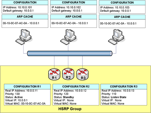
How does HSRP workHSRP works by two or more Routers agreeing upon which Router serves the virtual Router. HSRP ProtocolHSRP runs on top of UDP, and uses port number 1985. Packets are sent to multicast address 224.0.0.2 with TTL 1. The Virtual RouterThe Virtual Router is a MAC-address and a IP Address the active Router serves beside its configured IP address. If the active Router fails the standby Router becomes the Virtual Router by serving the virtual MAC-address and IP Address. If there are any Routers in speak state they will compete to be the new standby Router. HSRP exampleIn picture 1 three Routers R1,R2 and R3 are setup in a HSRP Group. The Virtual IP address 10.0.0.1 and virtual MAC-Address 00-10-0C-07-AC-0A are served by the active Router R1. R1 continuesly transmits hello packets to the standby Routers. |
Configuration of R1, R2 and R3
hostname R1 ! interface FastEthernet1/0 ip address 10.0.0.11 255.0.0.0 standby 10 priority 130 standby 10 preempt standby 10 timers 2 6 standby 10 ip 10.0.0.1 |
hostname R2 ! interface FastEthernet1/0 ip address 10.0.0.12 255.0.0.0 standby 10 priority 120 standby 10 preempt standby 10 timers 2 6 standby 10 ip 10.0.0.1 |
hostname R3 ! interface FastEthernet1/0 ip address 10.0.0.13 255.0.0.0 standby 10 priority 110 standby 10 preempt standby 10 timers 2 6 standby 10 ip 10.0.0.1 |
HSRP Group number
All the Routers in a HSRP Group must use the same Group number. In the example the Routers uses Group number 10. The group number ranges from 0 - 255. (Default is 0)
The virtual MAC-address
The virtual MAC-address is divided into three fields. In the example 00-10-0C-07-AC-0A
- 00-10-0C is the vendor code. (Cisco for example)
- 07-AC is a well-known HSRP code
- 0A is the HSRP group number 10 decimal is 0A hexadecimal
Priority
The priority are used to decide which Router should be the active Router and in which order the standby Routers will take over. The priority field can range from 0 - 255. (Default is 100)
If more Routers has the same priority the Router with the highest configured IP address will become the active Router.
Preempt
If a Router with a higher priority becomes operative in the HSRP group, the active Router will continue to be active regardless of the new Router having a higher priority. To have the new Router with the higher priority to take over operation as the active Router use the preempt statement.
Hello timers
HSRP Routers sends hello packets at regular intervals to each other.
- Hello packets are sent default every 3 second (Hello interval)
- Holdtime is default 10 seconds. (Time should be at least three times hello interval)
- Hello interval and holdtime could be learned by a standby Router from the active Router.
Tracking access Interfaces
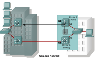
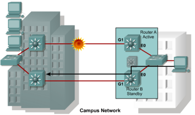
It is important to track the access interfaces.See Picture 2 below. Under normal operations where both WANS between the buildings are operational the active router routes packets between the buildings. If the WAN connected to the active Router fails the active Router should withdraw as active Router and let the standby Router take over. See Picture 3. Thats called tracking interfaces'
Configuring load balancing with HSRP
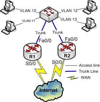
In the example below R1 will Route packets from VLAN 11 and VLAN 13 and R2 will Route packets from VLAN 10 and VLAN 12. If one of the routers fail, the other will take over. Interface tracking is configured as well. In the example below 20 will be substracted from priority if tracked interfaces fail.
hostname R1 ! interface FastEthernet0/0.10 encapsulation dot1Q 10 ip address 172.16.10.10 255.255.255.0 standby 10 ip 172.16.10.1 standby 10 preempt standby 10 priority 100 standby 10 track Serial0/0 20 ! interface FastEthernet0/0.11 encapsulation dot1Q 11 ip address 172.16.11.10 255.255.255.0 standby 11 ip 172.16.11.1 standby 11 preempt standby 11 priority 110 standby 11 track Serial0/0 20 ! interface FastEthernet0/0.12 encapsulation dot1Q 12 ip address 172.16.12.10 255.255.255.0 standby 12 ip 172.16.12.1 standby 12 preempt standby 12 priority 100 standby 12 track Serial0/0 20 ! interface FastEthernet0/0.13 encapsulation dot1Q 13 ip address 172.16.13.10 255.255.255.0 standby 13 ip 172.16.13.1 standby 13 priority 110 standby 13 preempt standby 13 track Serial0/0 20 |
hostname R2 ! interface FastEthernet0/0.10 encapsulation dot1Q 10 ip address 172.16.10.20 255.255.255.0 standby 10 ip 172.16.10.1 standby 10 preempt standby 10 priority 110 standby 10 track Serial0/0 20 ! interface FastEthernet0/0.11 encapsulation dot1Q 11 ip address 172.16.11.20 255.255.255.0 standby 11 ip 172.16.11.1 standby 11 preempt standby 11 priority 100 standby 11 track Serial0/0 20 ! interface FastEthernet0/0.12 encapsulation dot1Q 12 ip address 172.16.12.20 255.255.255.0 standby 12 ip 172.16.12.1 standby 12 preempt standby 12 priority 110 standby 12 track Serial0/0 20 ! interface FastEthernet0/0.13 encapsulation dot1Q 13 ip address 172.16.13.20 255.255.255.0 standby 13 ip 172.16.13.1 standby 13 priority 100 standby 13 preempt standby 13 track Serial0/0 20 |
Debugging HSRP
- Recommend use debug standby terse
Note
HSRP version 0 Brugere en opcode som ikke er beskrevet i RFC 2281, Nemlig opcode 3
Her er et indlæg fra et forum om det:
Here are some clippings from it. Cisco seems to have added this
opcode as part of the feature "HSRP Support for ICMP Redirects":
Passive HSRP Router Advertisements (opcode = 3)
Passive HSRP routers send out HSRP advertisement messages both periodically, and when entering or leaving the passive state. Thus, all HSRP routers can determine the HSRP group state of any HSRP router on the network. These advertisements inform other HSRP routers on the network of the HSRP interface state:
Dormant - interface has no HSRP groups, single advertisements sent once when last group is removed
Passive - interface has at least one non-active group and no active groups, advertisements sent out periodically
Active - interface has at least one active group, single advertisement sent out when first group becomes active


