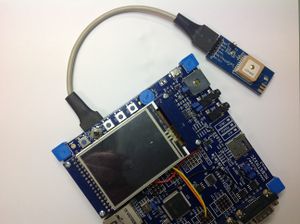
Difference between revisions of "GPS RECEIVER - MT3329"
From Teknologisk videncenter
m (→Data sheets) |
m (→Module on MCBSTM32C Keil board) |
||
| Line 3: | Line 3: | ||
Using the [[STM32F107VC]] remapped USART1 to PB6 (USART1_TX)and PB7 (USART1_RX). | Using the [[STM32F107VC]] remapped USART1 to PB6 (USART1_TX)and PB7 (USART1_RX). | ||
*The [http://www.keil.com/mcbstm32c/mcbstm32c-base-board-schematics.pdf|Schematics] show that PB6 is used for CAN2 bus TX. CAN2 bus can't be used at the same time as the GPS module. | *The [http://www.keil.com/mcbstm32c/mcbstm32c-base-board-schematics.pdf|Schematics] show that PB6 is used for CAN2 bus TX. CAN2 bus can't be used at the same time as the GPS module. | ||
| − | *The [http://www.keil.com/mcbstm32c/mcbstm32c-base-board-schematics.pdf|Schematics] show that PB7 is used for the USER button. To use PB7 as RX from the GPS module it is | + | *The [http://www.keil.com/mcbstm32c/mcbstm32c-base-board-schematics.pdf|Schematics] show that PB7 is used for the USER button. To use PB7 as RX from the GPS module it is necessary to remove C20. The USER switch can't be used at the same time as the GPS module. |
| + | ==Connections== | ||
| + | Solder a 6 pin 0,1 inch 90 degrees angle. See | ||
=Data sheets= | =Data sheets= | ||
Revision as of 09:40, 10 December 2013
Contents
Module on MCBSTM32C Keil board
Using the STM32F107VC remapped USART1 to PB6 (USART1_TX)and PB7 (USART1_RX).
- The [1] show that PB6 is used for CAN2 bus TX. CAN2 bus can't be used at the same time as the GPS module.
- The [2] show that PB7 is used for the USER button. To use PB7 as RX from the GPS module it is necessary to remove C20. The USER switch can't be used at the same time as the GPS module.
Connections
Solder a 6 pin 0,1 inch 90 degrees angle. See
Data sheets
ARM board projects
