Difference between revisions of "CCDA/Wireless LAN design"
m (New page: 400px|thumb|right|Industrial Scientific and medical Frequencies {|border=1 ;style="margin: 0 auto; text-align: center;cellpadding="5" cellspacing="0" |+ WLAN Standards su...) |
m |
||
| (7 intermediate revisions by the same user not shown) | |||
| Line 1: | Line 1: | ||
| − | [[Image:ISM.png|400px|thumb|right|Industrial Scientific and medical Frequencies]] | + | |
| + | |||
| + | =Materialer= | ||
| + | |||
| + | *[[Media:Netværksdesign_I_-_Chapter_4.pdf|Netværksdesign kapitel 4]] (Loads PDF) | ||
| + | == ISM and UNII frequencies == | ||
| + | === ISM === | ||
| + | [[Image:ISM.png|400px|thumb|right|Figure 1: Industrial Scientific and medical Frequencies in the 2,4 Gbps area]] | ||
| + | ISM - Industrial, Scientific and medical - frequencies are set aside by ITU-R radio regulations 5.138 and 5.150. In the U.S., the Federal Communications Commission (15.247) specifies the ISM bands for unlicensed use. Several bands are specified in the following ranges: | ||
| + | *900 to 928 MHz | ||
| + | *2.4 to 2.5 GHz | ||
| + | *5.75 to 5.875 GHz | ||
| + | Of these, channels located in the 2.4-GHz range are used for 802.11b and 802.11g. As shown in Figure 1, 11 overlapping channels are available for use. Each channel is 22 MHz wide. It is common to use channels 1, 6, and 11 in the same areas, because these three channels do not overlap. | ||
| + | |||
| + | === UNII === | ||
| + | The UNII - Unlicensed National Information Infrastructure - radio bands were specified for use with 802.11a wireless. UNII operates over three ranges: | ||
| + | *UNII 1—5.15 to 5.25 GHz and 5.25 to 5.35 GHz. | ||
| + | *UNII 2—5.47 to 5.725 GHz. This range is used by High Performance Radio LAN (HiperLAN) in Europe. | ||
| + | *UNII 3—5.725 to 5.875 GHz. This range overlaps with ISM. | ||
| + | UNII provides 12 nonoverlapping channels for 802.11a. | ||
| + | |||
{|border=1 ;style="margin: 0 auto; text-align: center;cellpadding="5" cellspacing="0" | {|border=1 ;style="margin: 0 auto; text-align: center;cellpadding="5" cellspacing="0" | ||
|+ WLAN Standards summary | |+ WLAN Standards summary | ||
| Line 16: | Line 36: | ||
|} | |} | ||
| + | = Cisco Unified Wireless Network = | ||
| + | UWN or Unified Wireless Network | ||
| + | {| | ||
| + | |[[Image:CCDA4 101.png|800px|thumb|right|Cisco Unified Wireless Network example]] | ||
| + | |} | ||
| + | [[WLAN controller Cisco]] | ||
| + | == LWAPP == | ||
| + | Lightweight Access Point Protocol (LWAPP) is a draft Internet Engineering Task Force (IETF) standard for control messaging for setup, authentication, and operations between access points (AP) and wireless LAN controllers (WLC). | ||
| − | + | With Cisco’s UWN Split-MAC operation, the control and data messages are split. Lightweight Access Points (LWAP) communicate with the WLCs using control messages over the wired network. LWAPP data messages are encapsulated and forwarded to and from wireless clients. The WLC manages multiple APs, providing configuration information and firmware updates as | |
| + | needed. | ||
| + | {| | ||
| + | |[[Image:CCDA4 102.png|600px|thumb|right|LWAPP]] | ||
| + | |} | ||
| + | == LWAPP Access Points == | ||
| + | LWAPP Access Points can operate in six different modes: | ||
| + | *'''Local mode''' —This is the default mode of operation. In this mode, every 180 seconds the AP spends 60 milliseconds on channels it does not operate on. During this 60 ms, the AP performs noise floor measurements, measures interference, and scans for IDS events. | ||
| + | *'''Remote Edge AP (REAP) mode''' —This mode enables an LWAP to reside across a WAN link and still be able to communicate with the WLC and provide the functionality of a regular LWAP. Currently, REAP mode is supported only on the 1030 LWAPs. | ||
| + | *'''Monitor mode''' —Monitor mode is a feature designed to allow specified LWAPP-enabled APs to exclude themselves from handling data traffic between clients and the infrastructure. They instead act as dedicated sensors for location-based services (LBS), rogue access point detection, and intrusion detection (IDS). When APs are in Monitor mode, they cannot serve clients and continuously cycle through all configured channels, listening to each channel for approximately 60 ms. | ||
| + | *'''Rogue detector mode''' —LWAPs that operate in Rogue Detector mode monitor the rogue APs. They do not transmit or contain rogue APs. The idea is that the rogue detector (RD) should be able to see all the VLANs in the network, because rogue APs can be connected to any of the VLANs in the network (thus, we connect it to a trunk port). The switch sends all the rogue AP/client MAC address lists to the RD. The RD then forwards those to the WLC to compare with the MAC addresses of clients that the WLC APs have heard over the air. If the MAC addresses match, the WLC knows that the rogue AP to which those clients are connected is on the wired network. | ||
| + | *'''Sniffer mode''' —An LWAPP that operates in Sniffer mode functions as a sniffer and captures and forwards all the packets on a particular channel to a remote machine that runs AiroPeek. These packets contain information on the time stamp, signal strength, packet size, and so on. The Sniffer feature can be enabled only if you run AiroPeek, a third-party network analyzer software that supports decoding of data packets. | ||
| + | *'''Bridge mode''' —The Bridge mode feature on the Cisco 1030 (typically indoor usage) and 1500 access points (typically outdoor mesh usage) provides cost-effective, high-bandwidth wireless bridging connectivity. Applications supported are point-to-point bridging, point-tomultipoint bridging, point-to-point wireless access with integrated wireless backhaul, and point-to-multipoint wireless access with integrated wireless backhaul. | ||
| + | == WLAN Authentication == | ||
| + | {| | ||
| + | |[[Image:CCDA4 103.png|600px|thumb|right| WLAN Authentication]] | ||
| + | |} | ||
| + | == WLAN Controller Components == | ||
| + | {| | ||
| + | |[[Image:CCDA4 104.png|600px|thumb|right| WLC overview]] | ||
| + | |} | ||
| + | {| | ||
| + | |[[Image:CCDA4 105.png|600px|thumb|right| WLC controller typer]] | ||
| + | |} | ||
| + | == Roaming == | ||
| + | === Intra-controller Roaming === | ||
| + | {| | ||
| + | |[[Image:CCDA4 106.png|600px|thumb|right| Intra-controller Roaming]] | ||
| + | |} | ||
| + | === Inter-controller Roaming === | ||
| + | {| | ||
| + | |[[Image:CCDA4 107.png|600px|thumb|right| Inter-controller Roaming - OSI Layer 2]] | ||
| + | |- | ||
| + | |[[Image:CCDA4 108.png|600px|thumb|right| Inter-controller Roaming - OSI Layer 3]] | ||
| + | |} | ||
| + | = Best practice = | ||
| + | *No more than 20 devices pr. AP | ||
| + | *If VoWLAN G711 Codec is used no more than 7 devices. | ||
| + | *If VoWLAN G729 Codec is used no more than 8 devices. | ||
{{#css: | {{#css: | ||
Latest revision as of 05:31, 8 May 2012
Contents
Materialer
- Netværksdesign kapitel 4 (Loads PDF)
ISM and UNII frequencies
ISM
ISM - Industrial, Scientific and medical - frequencies are set aside by ITU-R radio regulations 5.138 and 5.150. In the U.S., the Federal Communications Commission (15.247) specifies the ISM bands for unlicensed use. Several bands are specified in the following ranges:
- 900 to 928 MHz
- 2.4 to 2.5 GHz
- 5.75 to 5.875 GHz
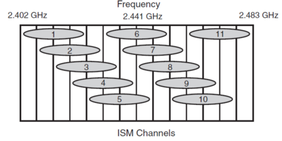
Of these, channels located in the 2.4-GHz range are used for 802.11b and 802.11g. As shown in Figure 1, 11 overlapping channels are available for use. Each channel is 22 MHz wide. It is common to use channels 1, 6, and 11 in the same areas, because these three channels do not overlap.
UNII
The UNII - Unlicensed National Information Infrastructure - radio bands were specified for use with 802.11a wireless. UNII operates over three ranges:
- UNII 1—5.15 to 5.25 GHz and 5.25 to 5.35 GHz.
- UNII 2—5.47 to 5.725 GHz. This range is used by High Performance Radio LAN (HiperLAN) in Europe.
- UNII 3—5.725 to 5.875 GHz. This range overlaps with ISM.
UNII provides 12 nonoverlapping channels for 802.11a.
| IEEE Protocol | Release | Frequency | Typical Data rate | Max. Data Rate |
|---|---|---|---|---|
| Legacy | 1997 | ISM | 1 Mbps | 2 Mbps |
| 802.11a | 1999 | UNII | 25 Mbps | 54 Mbps |
| 802.11b | 1999 | ISM | 6,5 Mbps | 11 Mbps |
| 802.11g | 2003 | ISM | 25 Mbps | 54 Mbps |
| 802.11n | 2007 (Draft) | ISM or UNII | 200 Mbps | 540 Mbps |
Cisco Unified Wireless Network
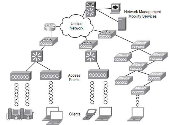
UWN or Unified Wireless Network
LWAPP
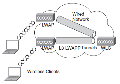
Lightweight Access Point Protocol (LWAPP) is a draft Internet Engineering Task Force (IETF) standard for control messaging for setup, authentication, and operations between access points (AP) and wireless LAN controllers (WLC).
With Cisco’s UWN Split-MAC operation, the control and data messages are split. Lightweight Access Points (LWAP) communicate with the WLCs using control messages over the wired network. LWAPP data messages are encapsulated and forwarded to and from wireless clients. The WLC manages multiple APs, providing configuration information and firmware updates as needed.
LWAPP Access Points
LWAPP Access Points can operate in six different modes:
- Local mode —This is the default mode of operation. In this mode, every 180 seconds the AP spends 60 milliseconds on channels it does not operate on. During this 60 ms, the AP performs noise floor measurements, measures interference, and scans for IDS events.
- Remote Edge AP (REAP) mode —This mode enables an LWAP to reside across a WAN link and still be able to communicate with the WLC and provide the functionality of a regular LWAP. Currently, REAP mode is supported only on the 1030 LWAPs.
- Monitor mode —Monitor mode is a feature designed to allow specified LWAPP-enabled APs to exclude themselves from handling data traffic between clients and the infrastructure. They instead act as dedicated sensors for location-based services (LBS), rogue access point detection, and intrusion detection (IDS). When APs are in Monitor mode, they cannot serve clients and continuously cycle through all configured channels, listening to each channel for approximately 60 ms.
- Rogue detector mode —LWAPs that operate in Rogue Detector mode monitor the rogue APs. They do not transmit or contain rogue APs. The idea is that the rogue detector (RD) should be able to see all the VLANs in the network, because rogue APs can be connected to any of the VLANs in the network (thus, we connect it to a trunk port). The switch sends all the rogue AP/client MAC address lists to the RD. The RD then forwards those to the WLC to compare with the MAC addresses of clients that the WLC APs have heard over the air. If the MAC addresses match, the WLC knows that the rogue AP to which those clients are connected is on the wired network.
- Sniffer mode —An LWAPP that operates in Sniffer mode functions as a sniffer and captures and forwards all the packets on a particular channel to a remote machine that runs AiroPeek. These packets contain information on the time stamp, signal strength, packet size, and so on. The Sniffer feature can be enabled only if you run AiroPeek, a third-party network analyzer software that supports decoding of data packets.
- Bridge mode —The Bridge mode feature on the Cisco 1030 (typically indoor usage) and 1500 access points (typically outdoor mesh usage) provides cost-effective, high-bandwidth wireless bridging connectivity. Applications supported are point-to-point bridging, point-tomultipoint bridging, point-to-point wireless access with integrated wireless backhaul, and point-to-multipoint wireless access with integrated wireless backhaul.
WLAN Authentication
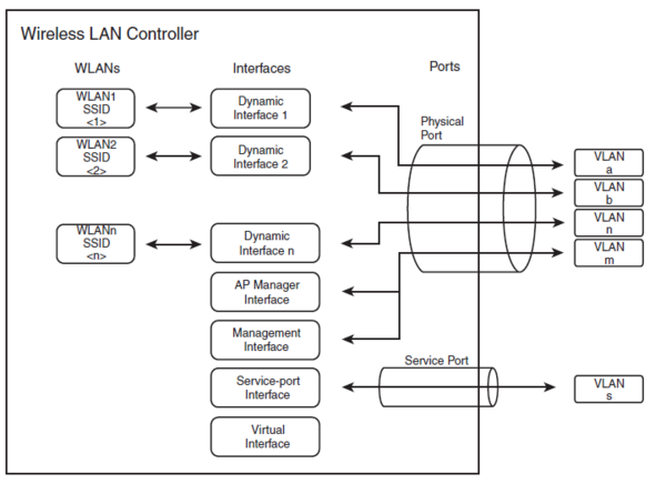
WLAN Controller Components
Roaming
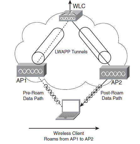
Intra-controller Roaming
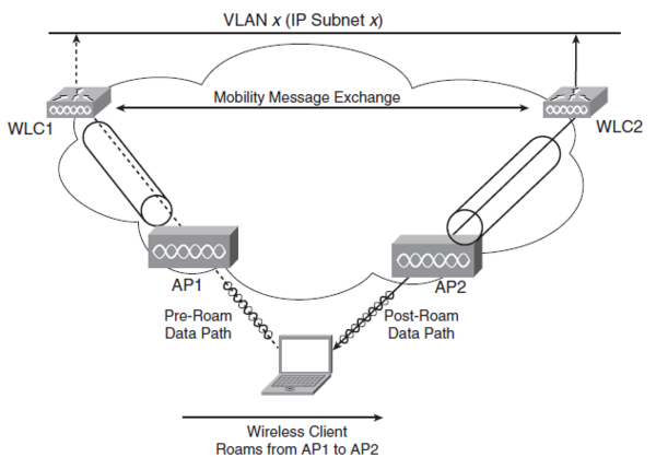
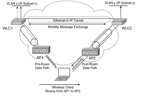
Inter-controller Roaming
Best practice
- No more than 20 devices pr. AP
- If VoWLAN G711 Codec is used no more than 7 devices.
- If VoWLAN G729 Codec is used no more than 8 devices.
