CCDA - en/Enterprise LAN design
Contents
Materials
- Network design chapter 3 (Loads PDF)
Reading plan
Unless you are preparing for the CCDA certification, you don't need to read the following subjects
- 10BASE5 and 10BASE2
- Token Ring
- Repeaters
- HUB
- Bridges
- 5-4-3 rule
LAN media
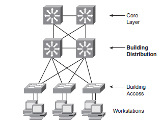
Best Pratice for Hierarchical Layers
Access Lag
- Configure VLAN Dynamic Trunking Protocol (DTP) to Desirable/Desirable with negotiation disabled.
- Prune VLAN manuelly to reduce broadcasts.
- Use VTP is transparant mode. No common VLAN database necessary.
- Disable Trunking on access ports. More swcurity and will make Portfast work faster.
- Consider using Routing in the Access Layer to get fast convergence and load-balancing.
A1(config-if)#<input>do show run int fa0/1</input>
interface FastEthernet0/1
 description Accessport USER
 no ip address
end

A1(config-if)#<input>switchport host</input>
switchport mode will be set to access
spanning-tree portfast will be enabled
channel group will be disabled

A1(config-if)#<input>do show run int fa0/1</input>
interface FastEthernet0/1
 description Accessport USER
 <notice>switchport mode access</notice>
 no ip address
 <notice>spanning-tree portfast</notice>
end
Distribution Layer
- Wire Speed on all ports.
- Link redundancy.
- Use FHRP for example HSRP or GLBP is using OSI layer 2 links to Access Switches.
- Use OSI Lag 3 links between Distribution and Core layer for faster convergens and load balancing.
- Use distributionsswitches to connect VLAN on more than one Access Switches.
- Summarize Routes from Distribution to Core layer reducing Routing overhead.
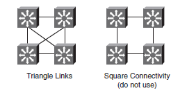
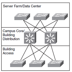
- Byg Layer 3 triangles, not squares, as shown on the diagram below.
Core Layer
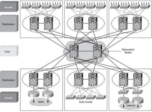
Dependent on the size of the network you could inplement a Core Layer. In Campus size network the Core Layer function is high-speed Layer 3 switching between the switch blocks.
- Use Layer 3 Switches in the Core Layer
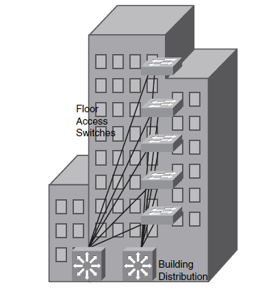
Network in big buildings
The Network in big buildings er segmented i floors and/or departments.
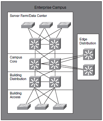
Enterprise Campus Network
A campus network connects to or more building in a limited geographical area. An Enterprise consists of two or more Campuses.
- Each building is assigned IP address spans allowing route summarization.
- Each campus is assigned IP address span allowing Campus Route summarization to reduce routing overhead.
- Design a logical IP address paln for example 10.campus.building.X or similar.
Edge distribution
- Edge distribution is the interface between a Campus and the surrounding world.
- Other Campuses in the same Enterprise
- VPN
- Internet
Edge Distribution protects Campus against:
- IP Spoofing (Edge Distribution Layer protects Core layer from announcing illegal IP addresses)
- Unauthorized access to the Core.
- Network Reconnaissance (Blocking trafic used by Crackers to recognder kan benyttes til at reconnoiter the network)
- Packet sniffers - (Separate Broadcast zones and limit traffic which can be sniffed)
Medium size networks
Medium sized network consists of 200 to 1000 network units. Distribution and Corelayer are often integrated in the same units. Called Collapsed Core.
Små netværk og opkobling af mindre filialer
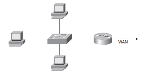
Mindre netværk og mindre filialer er ofte koblet op til hovedkontoret med en mindre Router. Routeren fjerner Broadcast trafik fra WAN forbindelsen.
Server Farm modul
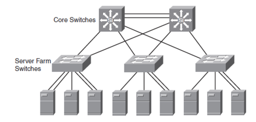
Server Farm modulet eller data centeret giver højhastigheds adgang til servere for Campuset. Servere tilsluttes Switche med 1 eller 10 Gbps Ethernet. I visse tilfælde anvendes EtherChannel
OPkobling af Servere
- Single NIC
- Dual NIC EtherChannel
- Content Switching (Flere servere er frontend)
Enterprise Data Center infrastructure
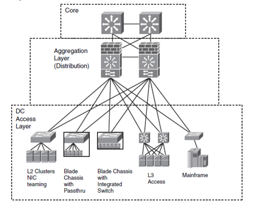
Data Centeret (DC) giver high performance/low latency lag 2 switching og supporterer servere med enkelte og dobbelte netkort. Det foretrukne design er lag 2 i access laget og lag 3 i distributionslaget. Blade Chassiss[1] med integrerede Switche er blevet en populær løsning.
Data center Aggregation Layer (Distribution Layer) aggregerer - samler trafikken - og
- Kan Load Balance trafikken mellem flere servere
- Kan offloade servere med SSL trafik ved at terminere krypteringen i enheder.
- Har Firewalls til at kontrollere adgangen.
- Har Intrusion Detection Services IDS
Campus LAN Quality of Service
Klassifikation og mærkning af QoS foregår i Access Laget og Enterprise Edge (ud mod verden) og indføre QoSpolitikker i Distributions laget.
Multicast trafik
Internet Group Management Protocol - IGMP - er en protokol som anvendes mellem hosts og den lokale Lag 3 switch. Hostene anvender IGMP stil at melde sig ind og ud af Multicast grupper - altså hvilke multicast datastrømme de ønsker at lytte til.
Når der anvendes Multicast i Campus er det vigtigt at overveje hvorledes Lag 2 Switche - Access lag - behandler Multicast. For at undgå lag 2 Switche sender multicast trafik ud af alle porte kan der anvendes CGMP eller IGMP Snooping.
